
USE OF INSTRUMENTS AND LETTERING
CLASSIFICATION OF LINES
Lines may be classified according to their thickness, darkness and shape:
Classification According to Thickness
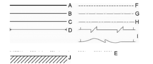
a ) Very thick lines drawn with chisel-shaped pencil Fig. 2.2 are used to show reinforcing
steel bars and position of beams etc. in structural working drawings, see Fig. 2.1 (A).
b ) Relatively thicker lines drawn with cone-shaped pencil Fig. 2.2, are used to show
ground level in elevation of buildings, plastered surfaces of walls in plans, etc., see Fig, 2.1 (B).
c) Lines of common thickness show usual features of the object see Fig. 2.1 (C).
d) Thin lines are used for center-lines, construction lines, extension lines, and
dimension lines, etc.
Classification According to Darkness
Line of a given thickness may be dark and bright or it may be dim depending upon grade of
the pencil and the pressure applied.
a) Thick and common lines should be of greater darkness and brightness keeping their
thickness in the required range. Generally try for greater brightness increases the thickness
of the line.
b ) Center -lines, extension lines and dimension lines should be of moderate
darkness, see Fig. 2.1 (D)
c ) Construction lines and guide lines should be very light or dim. Just liable to
working person.
Classification According to Shape
a) Full line of common thickness shows visible outline of the object, Fig. 2.1 (C), H-
Pencil is generally used for the purpose.
b) Full lines of lesser thickness and brightness are used as extension and dimension
lines. See Fig. 2.1 (D), 2H-Pencil may be used for the purpose.
c) Full lines of very dim quality, drawn with 4H-Pencil, are used as construction lines
and guide-lines.
d) Dotted line consists of a series of dots, as in Fig. 2.1 (E), and is not generally used in
engineering drawing because lot of time is consumed in drawing a dotted line.
e) Dashed line consists of a series of dashed lines as shown in figure 2.1 (F), the dashes
should approximately be equal in length and in gap between two dashes should
roughly be equal. Where dashed lines are in continuation of full lines, these should be
started from a gap, otherwise, these should be started
with a dash. These lines indicate hidden outlines in mechanical drawing but in civil
drawing, these lines, in plan, show the features above the cutting plane like
beams, sunshades and ventilators.
f) Center-lines consist of a series of alternate long and short dashes, as in Fig. 2.1
(G). These lines are used to locate centers of central parts and axes of
cylindrical features.
g) Cutting plane symbol is series of one long and two small dashes using
relatively thicker line, see Fig. 2.1 (H).
h) Break lines have different shapes, two of which are shown here, see Fig. 2.1 (I).
These lines are used to end a part of the structure to indicate the continuity of
structure in same pattern.
i) Section line or cross hatching consists of lines drawn at 45° 1/16" to 1/8", as in
It is used to indicate solid portions in section.


