Inserting Blocks in a Table
You can insert blocks in a table and fit inside the table cells. Note that you cannot insert Annotative
blocks in a table. The following example shows you to insert a block in a table.
Example:
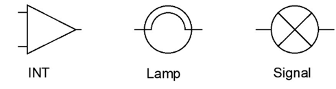
Create three blocks as shown below.
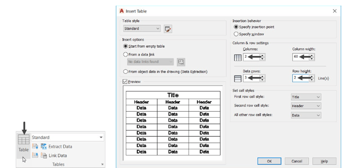
Click on Annotate > Table > Table from the Ribbon to display Insert Table dialog box.
Insert the values in the dialog box, as shown below.
Click OK and click anywhere in the drawing area to define the insertion point of the table, as
shown.
After inserting the table, you can change its size (width and height) uniformly by dragging
its corner grip, as shown below.
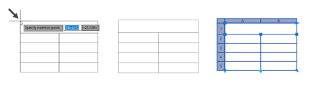
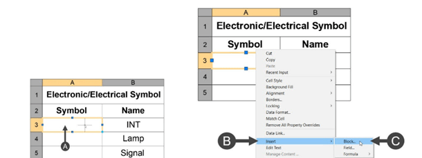
Enter the names in the table cells, as shown below.

Select the first cell in the Symbol row and right-click, as shown.
Select Insert > Block from the shortcut menu; the Insert a Block in a Table Cell dialog box appears.
In the Insert a Block in a Table Cell dialog box, select INT from the Name drop-down.
Set Overall cell alignment to Middle Center.
Click OK; the INT symbol will be placed in the selected cell.
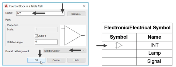
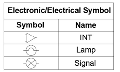
Similarly, insert the other symbols in the respected cells.
Using the Design Center
Design Center is one of the additional means by which you can insert
blocks and drawing in an effective way. Using the Design Center,
you can insert blocks created in one drawing into another drawing.
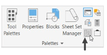
You can display the Design Center by clicking View > Palettes >
Design Center
on the ribbon or entering DC in the command line, as shown.
The following example shows you insert blocks using the DesignCenter.
Example:
Open a new drawing file.
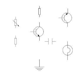
Create the following symbols and convert them into blocks.
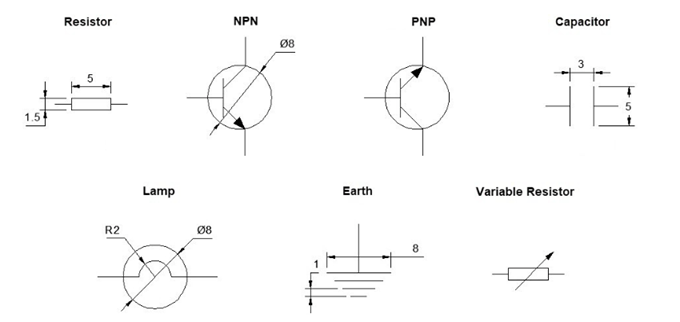
Save the file as Electronic Symbols.dwg. Close the file.
Open a new drawing file.
Set the maximum limit of the drawing to
100,100. Click Zoom All on the Navigation Bar.
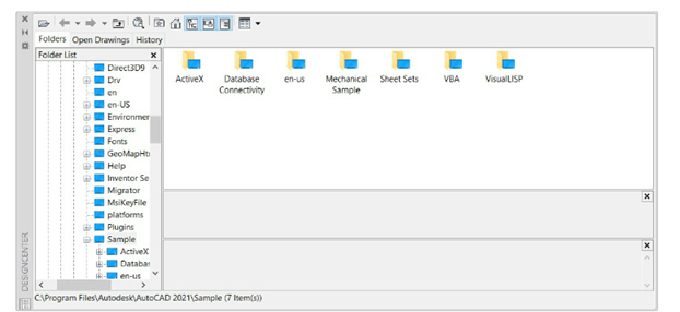
Click View > Palettes > DesignCenter
on the ribbon; the DesignCenter palette
appears.
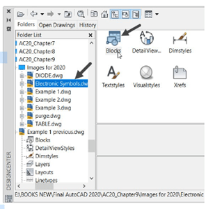
In the DesignCenter palette, browse to the
location of the Electronic Symbols.dwg file
using the Folder List, as shown.
Select the file and double-click on the Blocks
icon; all the blocks present in the file will be
displayed, as shown.
Drag and place the blocks in the drawing window.
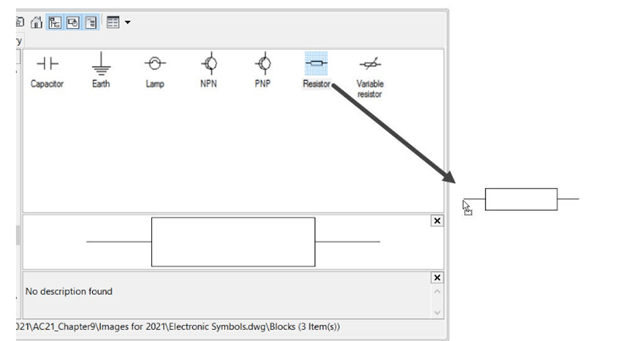
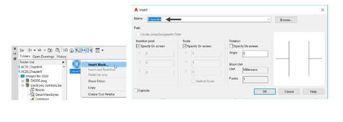
You can also insert blocks by invoking the Insert dialog box.
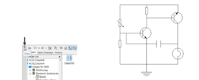
Use the Move and Rotate tools and arrange the blocks as shown below.
Close the DesignCenter palette, as shown.
Use the Line tool and complete the drawing as shown below.
Using Tool Palettes
You can arrange blocks, dimensions, hatch patterns and other
frequently used tools in Tool Palettes. Similar to the DesignCenter
palette, you can drag and place various features from Tool
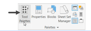
Palettes into the drawing. You can display the Tool Palettes by the
clicking View > Palettes > Tool Palettes on the ribbon or entering
TOOLPALETTES in the command line.
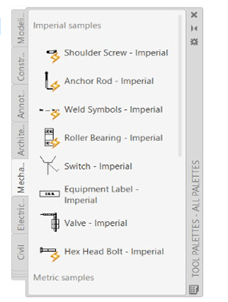
There are many palettes arranged in the TOOL PALETTES window.
You can display more palettes by clicking the lower left corner of the
Tool Palettes and selecting the required palettes.
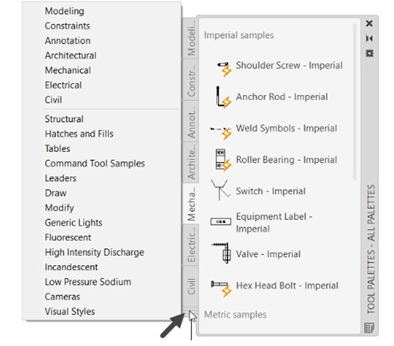
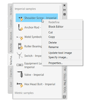
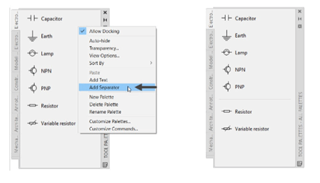
There are many blocks available in the Architectural, Mechanical, Electrical, Civil, and Structural
palettes. You can drag and place blocks from these palettes. You can also right-click on a block and
perform various operations using the shortcut menu displayed as shown below.
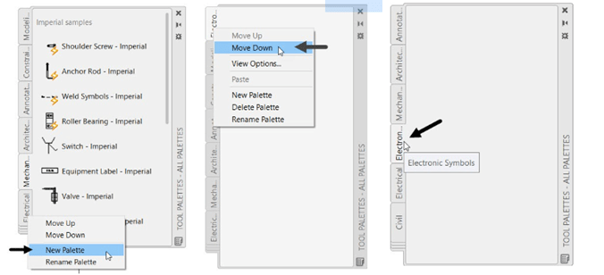
Creating a New Tool Palette
Right-click on the Tool Palette and select New Palette from the shortcut menu; a new palette
is added to Tool Palettes.
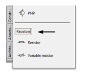
Enter Electronic Symbols as the name. The newly created Tool Palette get added, as shown.
Also, you can right click and select the Move Up and Move Down to change its location in
the TOOL PALETTES window, as shown.
You can also create a new tool palette using the Customize dialog box.
Right-click on Tool Palettes and select Customize Palettes; the Customize dialog box appears, as
shown.
In the Customize dialog box, right-click in the Palettes list and select New Palette.
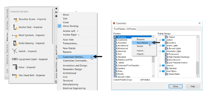
Enter the name of the palette and click the Close button.
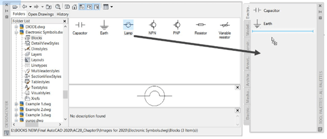
Adding Blocks to a Tool Palette
Open the DesignCenter palette and select the Electronic Symbols.dwg file from the
Folders list; the blocks available in the selected file are displayed.
Drag the blocks from the DesignCenter and place them in the Tool Palette.
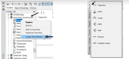
You can also create a new tool palette from a drawing consisting of blocks.
In the DesignCenter palette, select the Electronic symbols.dwg file from Folder List.
Right-click and select Create Tool Palette; a new palette will be created from the drawing file.
In the Tool Palette, you can group blocks depending on their function.
Right-click on the Tool Palette and select Add Separator; a separator will be added.
Right-click and select Add Text. Enter the name of the group.
Inserting Multiple Blocks
You can insert multiple instances of a block at a time by using the MINSERT command. This
command is similar to the ARRAY command. The following example explains the procedure to insert
multiple blocks at a time.
Example:
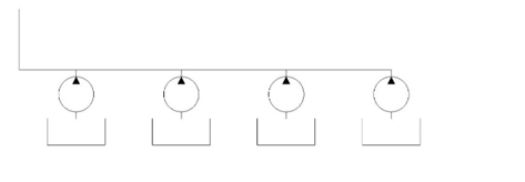
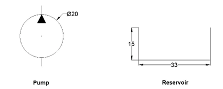
Create two blocks as shown below.
Type MINSERT in the command line and press ENTER; the message, “Enter block name or [?]:”
appears.
Type Pump and press ENTER; the Pump is attached to the cursor.
Pick a point in the drawing window.
Enter 1 as the scale factor.
Enter 0 as the rotation angle; the message, “Enter number of rows (—) <1>:” appears.
Enter 1 as the row value; the message, “Enter number of columns (|||) <1>:” appears.
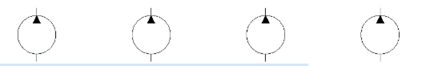
Enter 4 as the column value; the message, “Specify distance between columns (|||):” appears.
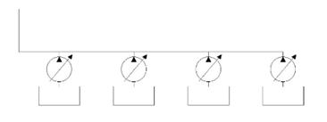
Type 60 and press ENTER; the pumps will be inserted as shown below.
Similarly, insert the reservoirs and create lines as shown below.
Editing Blocks
During the design process, you may need to edit blocks. You can easily edit a block using the Block
Editor window. As you edit a block, all the instances of it will be automatically updated. The
procedure to edit a block is discussed next.
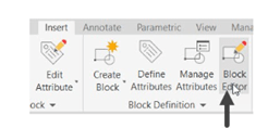
Click Insert > Block Definition > Block Editor on the ribbon; the Edit Block Definition dialog box
appears.
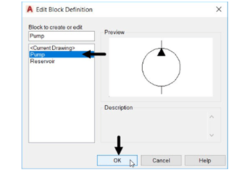
In the Edit Block Definition dialog box, select Pump from the list and click OK; the Block
Editor window appears.
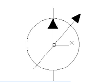
Click Home > Draw > Polyline on the ribbon and draw a polyline as shown below.
Click Close Block Editor on the Close panel.

In the Block – Changes Not Saved dialog box, click Save the changes to Pump.
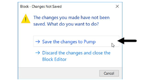
All the instances of the block will be updated automatically.