Editing Dimensions using Grips
In Chapter 4, you have learned to edit objects using grips. In the same away, you can edit dimensions
using grips. The editing operations using grips are discussed next.
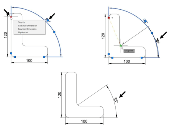
Example: (Stretching the Dimension)
Select the dimension to display grips on it.
Select the endpoint grip of the dimension.
Next, move the cursor and select a new point; the dimension value will be updated, automatically.
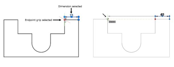
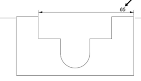
You can also stretch angular or radial dimensions.
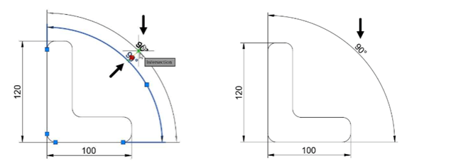
Example: (Moving the Dimension)
To move a linear dimension, select the middle grip and move the cursor.

Similarly, you can move the angular and radial dimensions.
Example: (Modifying the Dimension text)
Select the dimension and place the cursor on the middle grip; a shortcut menu appears as shown below.
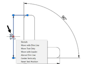
The options in the menu are self-explanatory. You can perform the required operation by selecting the corresponding option.
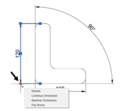
Similarly, place the cursor on the endpoint of the dimension line and select the required option from the menu.
Modifying Dimensions using the Properties palette
Using the Properties palette, you can modify the dimensional properties such as text, arrow size,
precision, linetype, lineweight, and so on. The Properties palette comes in handy when you want to
modify the properties of a particular dimension only.
Example:
Create the drawing shown in figure and apply dimensions to it.
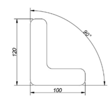
Select the vertical dimension and right-click.
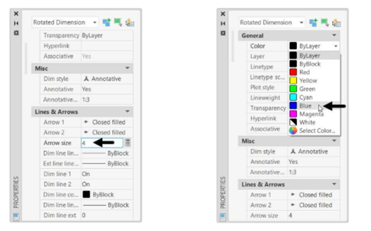
Select Properties from the shortcut menu; the Properties palette appears.
In the Properties palette, under the Lines & Arrows section, set the Arrow size to 4, as shown.
Under the General section, set Color to Blue, as shown.
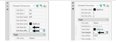
Set the Ext line offset value to 2.
Scroll down to the Text section and set Text height to 4.
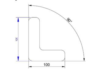
Close the Properties palette; you will notice that the properties of the dimension are updated
as per the changes made.
Matching Properties of Dimensions or Objects
In the previous section, you have learned to change the properties of a dimension. Now, you can apply
these properties to other dimensions by using the Match Properties tool.
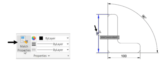
Click Home > Properties > Match Properties from the ribbon or type MA and press ENTER;
the message, “Select source object” appears in the command line.
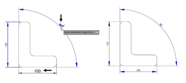
Select the vertical dimension from the drawing; the message, “Select destination object(s) or
[Settings]:” appears in the command line.
Select the Settings option from the command line; the Property Settings dialog box appears.
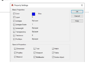
In this dialog box, you can select the settings that can be applied to the destination dimensions or
objects. By default, all the options are selected in this dialog box.
Click OK from the Property Settings dialog box. Next, you need to select the destination objects.
Select the other dimensions from the drawing; the properties of the source dimension are
applied to other dimensions.
Right-click and select Enter.
Questions:
1. Which tool is used to create vertical or horizontal dimensions?
2. Which tool is used to create total length of an arc?
3. Which tool is used to create radial dimension?
4. Which tool is used to dimension one or more dimensions at the same time?
5. Which command is used to modify dimensions?
6. Which tool is used to incline the extension lines of a dimension?
7. Which tool is used to match properties of dimensions or objects?
Exercises
Exercise 1:
Create the drawing shown below and create hole callouts for different types of holes. Assume
missing dimensions.
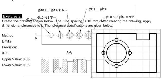
Exercise 2:
Create the drawing shown below. The Grid spacing is 10 mm. After creating the drawing, apply
dimensional tolerances to it. The tolerance specifications are given below.
Method:
Limits
Precision:0.00
Upper Value: 0.05 Lower Value: 0.05
Exercise 3:
Create the following drawings and apply dimensions and annotations. The Grid Spacing X= 10 and Grid Spacing Y=10.


