ARRANGEMENT OF VIEWS
Upto this stage, it has been discussed how top view, front view and end view can be
obtained on horizontal, frontal and profile planes respectively. Now consider an
object to be placed inside a box of picture planes as shown in Fig. 3.7 (A). The three
orthographic views are also shown on the respective planes, that means, we have
transformed the three dimensional shape of the object into two dimensional views. Still
these views, although two dimensional, are lying in three dimensions and cannot be
shown on a drawing paper. For that the profile plane is rotated through 90° ,
considering the intersection of the profile and the frontal planes as pivot, such that, the
end view comes in the frontal plane, see Fig. 3.7 (C). Also horizontal plane is rotated
about its intersection with the frontal plane, such that, the top view also comes in the
frontal plane.
These views may now be drawn on a drawing paper, as shown in Fig. 3.7 (D), which
shows the arrangement of views in third angle projection. When a horizontal and a
vertical plane of projection are intersecting at right angle to each other, four
quadrants are formed, as shown in Fig. 3.8 (A). The object is assumed to be placed in any of these quadrants and viewing is always considered from the top and from the right.
For third angle projection, the object is positioned in third quadrant, as shown in Fig. 3.8
(B) , and arrangement of views already shown in Fig. 3.7 is obtained.
For complete description of the object, an additional vertical plane is used at 90 ° to the
principal planes over which the E.V. is formed. In this arrangement of views, picture
plane is always considered in between the observer and the object as in Fig. 3.8 (D).
Exactness of views and their proper arrangement are equally important, if the views are
drawn at different positions not according to certain fixed conventions, the shape will be wrongly Communicated because the reader will imagine the views to be rotated to
their original position to conceive the shape of the object. It is important to note
that actually, for the object, bottom line of the top view and top line of the front view
coincide and top view is actually going inside the drawing paper according to the
width dimension. Similarly, end view should also be considered as going inside the
drawing paper.
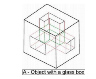
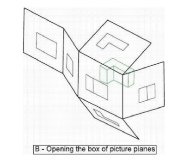
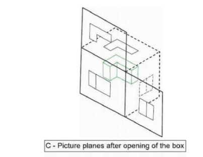
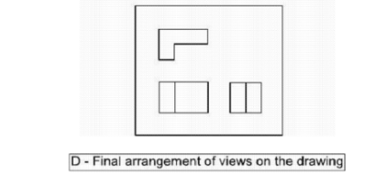
Fig. 3.7 Arrangement of Views in 3rd Angle Projection
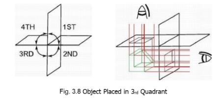
Fig. 3.8 Object Placed in 3rd Quadrant
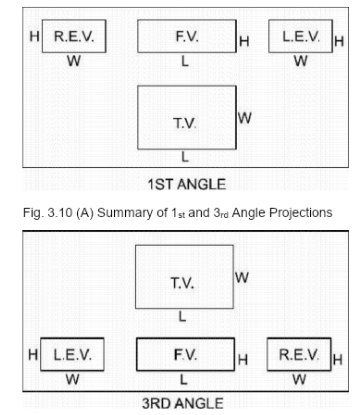
To summarize, in third angle projection, front view is always drawn at the bottom, top
view just above the front view, and end view is drawn on that side of the front view
from where we are looking at the end of the object relative to the front. L.E.V should be
accommodated on the left of F.V while R.E.V on the right of F.V, however, one E.V is
generally drawn.
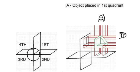
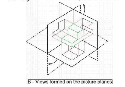
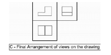
Fig. 3.9 Arrangement of Views in 1st Angle Projection
For first angle projection, the object is positioned in first quadrant as shown in Fig. 3.9
(A) and, hence, the object is considered to be in between the picture plane and the
observer. After forming the views on the three planes, as shown in B-part of the figure,
the top and the end views are rotated through 90° as before until they come in the
frontal plane giving the final arrangement of views as shown in C-part of the figure. Top
view is drawn at bottom of the

Fig. 3.10 (B) Summary of 1st and 3rd Angle Projections
paper, front view just above it and end view is drawn on that side of the front view which is opposite to the side from which we are looking at the object relative to the front.
First-angle projection was originally used all over the world but now in countries like the United States and Canada, third-angle projection is standard. In Pakistan, we use first angle projection for building drawing because all of the previous drawings for important buildings still lying in the offices are according to this method. For machine drawing, more trend is to use third-angle projection because of its convenience and because most of the machines are imported from those 4countries which have third-angle projection as standard.


