Working with External references
In AutoCAD, you can attach a drawing file, image or a pdf file to another drawing. These
attachments are called External References (Xrefs). They are dynamic in nature and update
automatically when changes are made to them. The following example, you will learn to attach
drawing files to a drawing.
Example:
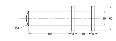
Create the drawing shown below.
Type BASE in the command line and press ENTER.
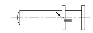
Select the midpoint of the vertical line as the base point, as shown.
Save the drawing as Crank pin.dwg
Create another drawing as shown below.
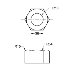
Use the Set Base Point tool and specify the base point as shown below.
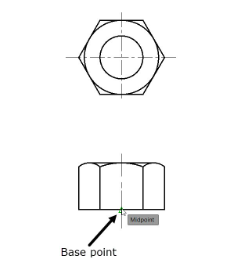
Save the drawing as Nut.dwg and close it.
Open the Crank.dwg file created in Chapter 8.
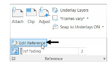
Click Insert > Reference > Attach on the ribbon; the Select
Reference file dialog box appears.
Browse to the location of the Crankpin.dwg and double-click on it; the Attach External
Reference dialog box appears.
Some of the options available in this dialog box are similar to that in the Insert dialog box, such as the insertion point, scale, and rotation angle of the external reference.
Accept the default settings in this dialog box and click OK; the crank pin will be attached to the cursor.

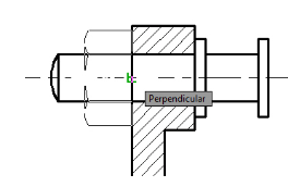
Select the point on the section view as shown below.

Click View > Palettes > External References Palette on the ribbon; the External
References Palette appears. This palette displays the Xrefs attached to the drawing.
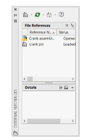
In the External References palette, open the Attach drop-down and select the Attach DWG
option; the Select References file dialog box appears.
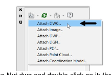
Browse to the location of the Nut.dwg and double-click on it; the Attach External Reference dialog box appears
In the Attach External Reference dialog box, enter 90 in the Angle box under the Rotation
group and click OK.
Select the insertion point on the section view as shown below.
