
Defining Attributes
An attribute is a line of text attached to a block. It may contain any type of information related to a
block. For example, the following image shows a Compressor symbol with an equipment tag. The
procedure to create an attribute is discussed in the following example.
Example:
Open a new drawing file.
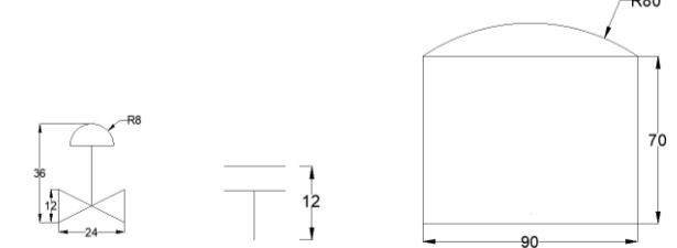
Create the symbols as shown below.
Click Insert > Block Definition > Define Attributes on the ribbon; the Attribute Definition dialog box appears.
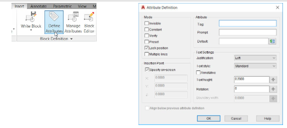
The options in the Mode group of the Attribute Definition dialog box are used to set the display mode
of the attribute. If you select the Invisible option, the attribute will be invisible. The Constant option
makes the value of the attribute constant. You cannot change the value. The Verify option prompts
you to verify after you enter a value. The Preset option allows you to set a predefined value for the
attribute. The Lock position option fixes the position of the attribute to a selected point. The Multiple
lines option allows typing the attribute value in single or multiple lines.
Ensure that the Lock position option is selected.
The options in the Attribute group are used to specify the values of the attribute. The Tag box is used to enter the label of the attribute. For example, if you want to create an attribute called RESISTANCE, you need to type Resistance in the Tag box. The Prompt box is used to specify the prompt message that appears after placing the block. The Default box is used to specify the default value of the attribute.
In the Attribute Definition dialog box, enter Valvetag in the Tag box.
The Text Settings options are used to specify the display properties of the text such as style, height
and so on. Observe the other options in this dialog box. Most of them are self-explanatory.
Enter 4 in the Text Height box.
Set the Justification to Middle and click OK.
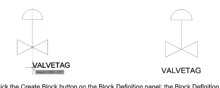
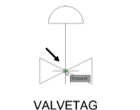
Specify the location of the attribute as shown below.
Click the Create Block button on the Block Definition panel; the Block Definition dialog box appears.
Click on the Select Object button from the dialog box.
Drag a window and select the control valve symbol and attribute. Press ENTER.
Select the Delete option from the Objects group.
Click the Pick Point button under the base point group and select the point as shown below.
Enter Control Valve in the Name box and click OK.
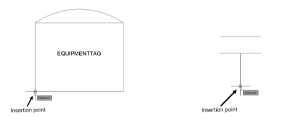
Similarly, create Equipmenttag and place inside the tank symbol.
Create a block and name it as Tank, as shown.
Also, create a block of the nozzle symbol and name it Nozzle, as shown.
Note: If you want to use these blocks in any other drawings then instead of using Create Block


