Drawing Circles
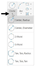
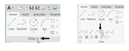
You can draw circles using the tools available in the Circle drop-down of the
Draw panel. You can also type the CIRCLE command in the command line and
create various types of circles. There are various methods to create circles.
These methods are explained in the following examples.
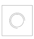
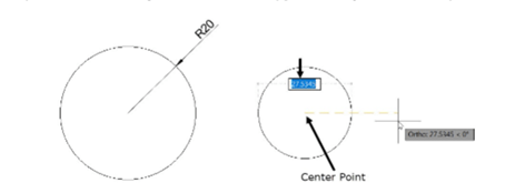
Example (Center, Radius):
In this example, you will create a circle by specifying its center and radius value.
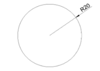
Click Home > Draw > Circle > Center, Radius on the ribbon.
Click at an arbitrary point in the drawing window to specify the center point.
Type 20 as the radius and press ENTER.
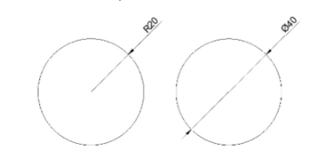
Example (Center, Diameter):
In this example, you will create a circle by specifying its center and diameter value.
Click Home > Draw > Circle > Center, Diameter on the ribbon; the message,
“Specify center point for circle or [3P 2P Ttr (tan tan radius)]:” appears in the command line.
Pick a point in the drawing window which is approximately horizontal to previous circle.
Type 40 as the diameter and press ENTER; the circle will be created, as shown.
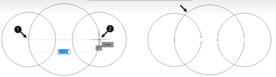
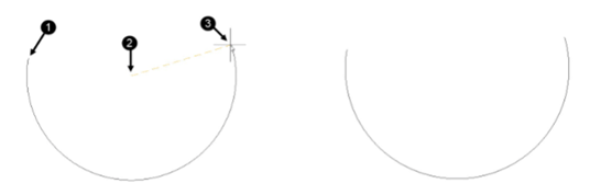
Example (2-Point):
In this example, you will create a circle by specifying two points. The first point is to specify the
location of the circle and the second defines the diameter.
Click Home > Draw > Circle > 2-Point on the ribbon; the message, “Specify first
end point of circle's diameter:” appears in the command line.
Now, you will create a circle by selecting the center points of the previous circles.
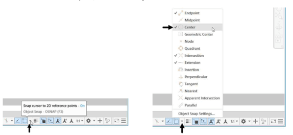
Click on the down arrow next to the Object Snap button on the status bar to display the flyout.
The options in this flyout are called Object Snaps. You will learn about these Object Snaps
later in Chapter 3.
Activate the Center option, if it is not already active.
Select the center point of the left side circle; the message, “Specify second end point of
circle's diameter:” appears in the command line.
Select the center point of the right-side circle; the circle will be created a shown below.
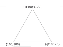
Example (3-Point):
In this example, you will create a circle by specifying three points. The circle will pass through these
three points.
Open a new file.
Use the Line tool and create the drawing shown in figure below. The coordinate points are
also given in the figure.
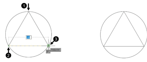
Click Home > Draw > Circle > 3-Point on the ribbon.
Select the three vertices of the triangle; a circle will be created passing through the selected points.
Example (Tan, Tan, Radius):
In this example, you will create a circle by selecting two objects to which it will be tangent, and then
specifying the radius of the circle.
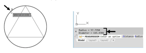
Click Home > Utilities > Measure > Radius on the ribbon; the message, “Select arc
or circle:” appears in the command line.
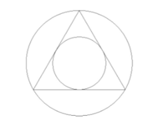
Select the circle passing through the three vertices of the triangle; the radius and diameter
values of the circle will be displayed above the command line, as shown.
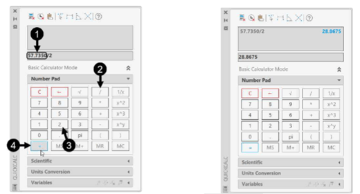
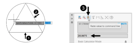
Double click Home > Utilities > Quick Calculator on the ribbon; the Quick Calculator appears.
Type 57.7350 in the Quick Calculator, as shown.
Click the “/” button and then the “2” button on the Number Pad, as shown.
Click the “=” button; the value 28.8675 is displayed in the value box, as shown.
 Click Home > Draw > Circle > Tan, Tan, Radius on the ribbon; the
message, “Specify point on object for first tangent of circle:” appears in the command line.
Select the horizontal line of the triangle; the message, “Specify point on object for second
tangent of circle:” appears in the command line.
Select anyone of the inclined lines; the message, “Specify radius of circle” appears in the command
line.
Click the Paste value to command line button on the Quick Calculator; the value 28.8675 will
be pasted in the command line.
Press ENTER to specify the radius; the circle will be created touching all three sides of the triangle.
Save and close the file.
Example (Tan, Tan, Tan):
In this example, you will create a circle by selecting three objects to which it will be tangent.
Click the Open button on the Quick Access Toolbar; the Select File dialog box appears.
Browse to the location of Line-example3.dwg file and double-click on it; the file will be opened.
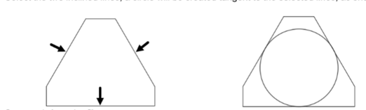
Click Home > Draw > Circle > Tan, Tan, Tan on the ribbon.
Select the bottom horizontal line of the drawing.
Select the two inclined lines; a circle will be created tangent to the selected lines, as shown.
Save and close the file.
Drawing Arcs
An arc is a portion of a circle. The total angle of an arc will always be less
than 360 degrees, whereas the total angle of a circle is 360 degrees.
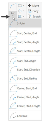
AutoCAD provides you with eleven ways to draw an arc. You can draw arcs
in different ways by using the tools available in the Arcs drop-down of the
Draw panel. The usage of these tools will depend on your requirement.
Some methods to create arcs are explained in the following examples.
Example (3-Point):
In this example, you will create an arc by specifying three points. The arc
will pass through these points.
Open the Line-example1.dwg file, previous created.
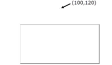
Expand the Draw panel in the Home tab and then select the Multiple
Points tool, as shown.
Type 100,120 in the command line and press ENTER; the point will be placed above the rectangle.
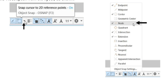
Click on the drop-down next to the Object Snap button on the status bar, and then select
the Node option from the flyout, as shown.
Click Home > Draw > Arc > 3-Point on the ribbon; the message, “Specify start point
of arc or [Center]:” appears in the command line.
Select the top left corner of the rectangle.
Select the point located above the rectangle.
Select the top right corner of the rectangle; the three-point arc will be created.

Example (Start, Center, End):
In this example, you will draw an arc by specifying its start, center and end points. The first two
points define the radius of the arc and third point defines its included angle.
Click Home > Draw > Arc > Start, Center, End on the ribbon; the message, “Specify start
point of arc or [Center]:” appears in the command line.
By default, the arc will be created in Counter-clockwise direction. Press and hold the CTRL
key if you want to switch the direction.
Pick an arbitrary point in the drawing window to specify the start point of an arc; the message,
“Specify center point of arc:” appears.
Pick a point to define the radius of the circle. You can also type the radius value and press
ENTER; the message, “Specify end point of arc or [Angle chord Length]:” appears.
You will notice that, as you move the cursor, the included angle of the arc changes.
Pick a point to define the included angle of the arc. You can also type the angle value and
press ENTER; the arc will be created.
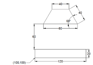
Example (Start, End, Direction):
Use the Line tool and create the drawing shown in figure below. The dimensions are also
given in the figure.
Click Home > Draw > Arc > Start, End, Direction on the ribbon.
Select the start and end points of the arc as shown in figure.
Move the cursor vertically downward and click to specify the direction; the arc will be created.
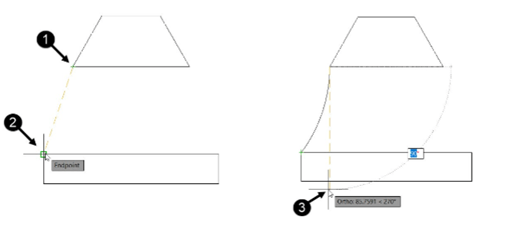
Similarly, create another arc, as shown.