Adding Leaders
A Leader is a thin, dark, solid line terminating with an arrowhead at one end and a dimension, note, or
symbol at the other end. In the following example, you will learn to create a leader style, and then
create a leader.
Example:
Draw a square of 24 mm length.
Create a circle of 10.11 mm diameter at center of the square.
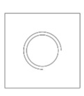
Click Home > Draw > Arc > Center, Start, Angle on the ribbon.
Select the center point of the circle.
Move the cursor horizontally toward right.
Type 6 as the radius and press ENTER.
Type 270 as the included angle and press ENTER.
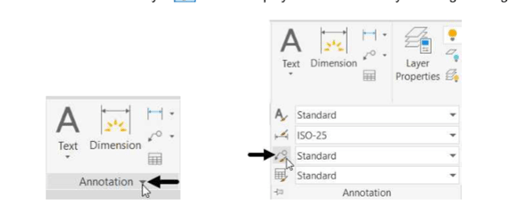
Click on the down arrow of the Annotation panel in Home tab to expand it, as shown.
Click on the Multileader Style icon to display the Multileader Style Manager dialog box.
Click on the New button of the Multileader Style Manager dialog box; the Create New
Multileader Style dialog box get visible.
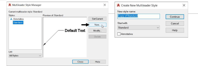
In the Create New Multileader Style dialog box, enter Hole callout in the New style name edit
box and select Standard from the Start with drop-down.
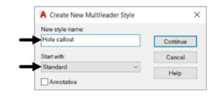 Click on the Continue button; the Modify Multileader Style dialog box get visible.
Under the Leader Format tab, set the Arrowhead Size to 2.5.
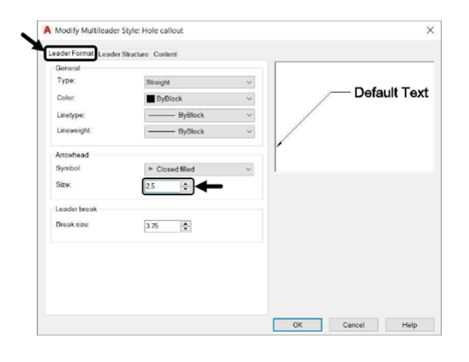
The other options in this tab are used to set the appearance of the multileader lines and the arrow head.
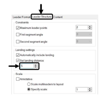
Click on the Leader Structure tab and set the Landing distance to 5.
Click on the Content tab and set the Text height to 2.5.
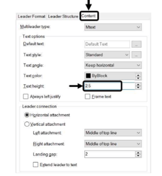
The other options in this tab are used to define the appearance of the text or block that will be
attached at the end of the leader line.
Click OK from the Modify Multileader Style dialog box.
Click Set Current from the Multileader Style Manager dialog box.
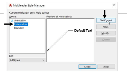
Click Close to close the dialog box.
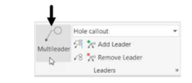
Click Annotate > Leaders > Multileader on the ribbon.
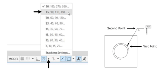
Click on the down-arrow with the Polar tracking button at the status bar and select 45 from the menu.
Select a point in the first quadrant of the arc.
Move the cursor in the top right direction and click to create the leader.
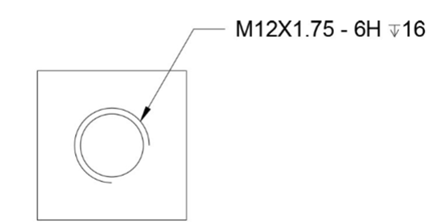
Type M12X1.75 – 6H 16 in the text editor.
Next, you need to insert the depth symbol before 16.
Place the cursor before 16 and click the Symbol button on the Insert panel of the Text Editor
ribbon; a menu appears.
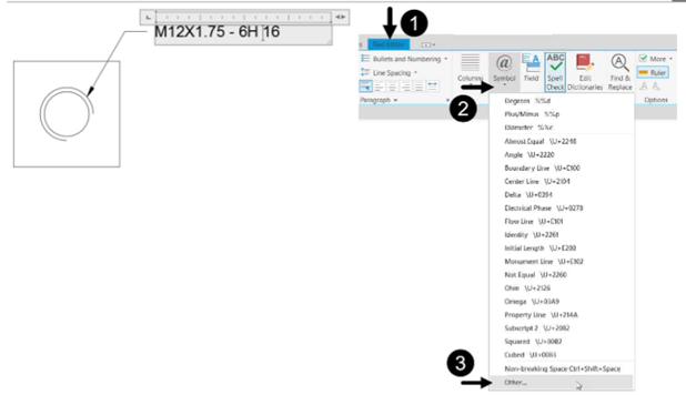
Click Other on the menu; the Character Map dialog box appears.
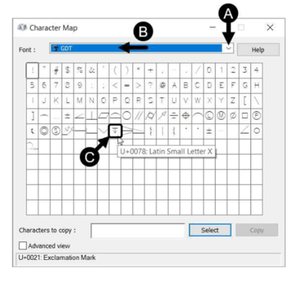
In the Character Map dialog box, select GDT from the Font drop-down.
Select the Depth symbol from the fonts table.
Click Select and Copy buttons.
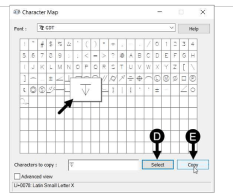
Close the Character Map dialog box.
Right-click and select Paste; the depth symbol is pasted in the text editor.
Adjust the spacing so that the complete text is in one line.
Adding Dimensional Tolerances
During the manufacturing process, the accuracy of a part is an important factor. However, it is
impossible to manufacture a part with the exact dimensions. Therefore, while applying dimensions to
a drawing we provide some dimensional tolerances which lie within acceptable limits. The following
example shows you how to add dimension tolerances in AutoCAD.
Example:
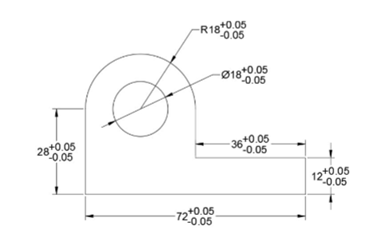
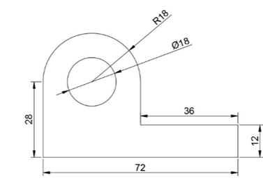
Create the drawing as shown below. Do not add dimensions to it.
Create a new dimension style with the name Tolerances.
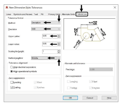
In the New Dimension Styles dialog box, click the Tolerances tab.
In the Tolerances tab, set the Method as Deviation.
Set Precision as 0.00.
Set the Upper Value and Lower Value to 0.05.
Set the Vertical Position as Middle.
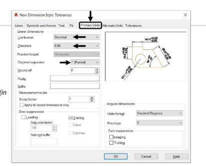
Specify the following settings in the Primary Units, Text, and Symbols and Arrows tab, as shown:
Primary Units tab:
Unit format: Decimal
Precision: 0.00
Decimal Separator: ‘.’Period
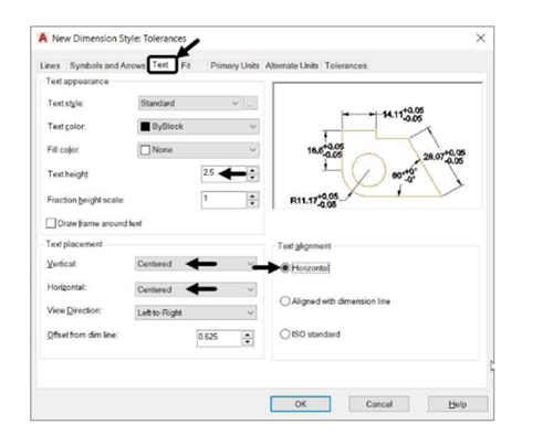
Text tab:
Text height: 2.5
Text placement: Centered (in
Vertical & Horizontal)
Text alignment: Horizontal
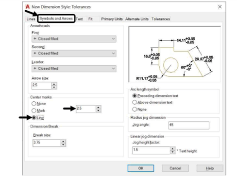
Symbols and Arrows tab:
Arrow Size: 2.5
Center marks: Line
Click OK from New Dimension Styles dialog box.
Click Set Current and Close on the Dimension Style Manager dialog box.
Apply dimensions to the drawing.