Drawing Splines
Splines are non-uniform curves which are used to create irregular shapes. In AutoCAD, you can
create splines by using two methods: Spline Fit and Spline CV. These methods are explained in the
following examples:

Example ( Spline Fit):
In this example, you will create a spline using the Spline Fit method. In this method, you need to specify
various points in the drawing window. The spline will be created passing through the specified points.
Start a new drawing file.
Use the Line tool and create a sketch similar to the one shown below.
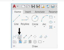
Expand the Draw panel in the Home tab and select the Spline Fit button; the message,
“Specify first point or [Method Knots Object]:” appears in the command line.

Select the lower-left corner of the sketch; the message, “Enter next point or [start
Tangency toLerance]:” appears in the command line.
Select the top-left corner point of the sketch.
Similarly, select the top-right and lower-right corners; a spline will be attached to the cursor.
Press ENTER to create the spline.

Example: ( Spline CV):
In this example, you will create a spline by using the Spline CV method. In this method, you will
specify various points called control vertices. As you specify the control vertices, imaginary lines are
created connecting them. The spline will be drawn tangent to these lines.
Expand the Draw panel in the Home tab and select the Spline CV button.

Select the four corners of the sketch in the same sequence as in the earlier example.
Press ENTER; a spline with control vertices will be created.


