
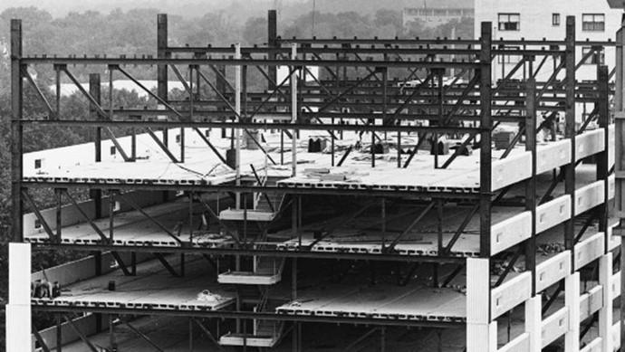
11 STEEL FRAME CONSTRUCTION
HISTORY
Making steel was labor intensive
Use of steel was limited to weapons (e.g., Damascus steel swords), cutlery, other specialties
1750 and later

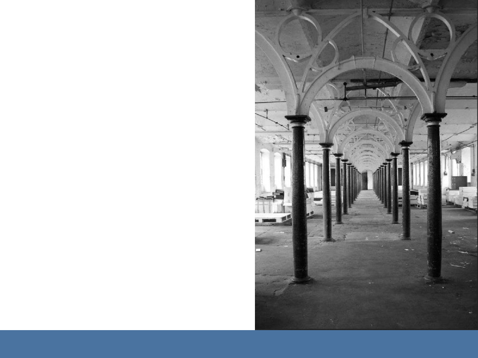
Growth in use of cast iron framing in industrial buildings and other structures
Right: Coalbrookdale Bridge, 1779, first all-metal structure
Fundamentals of Building Construction, Materials & Methods, 6th Edition
Copyright © 2013 J. Iano. All rights reserved.
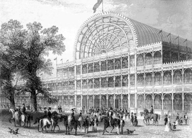
Right: Crystal Palace, 1851; cast iron and glass
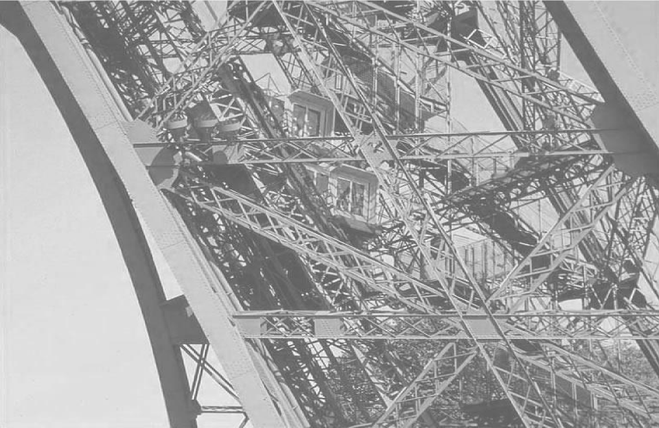
Eiffel Tower, 1889 Wrought iron
Fundamentals of Building Construction, Materials & Methods, 6th Edition
Copyright © 2013 J. Iano. All rights rese
1850 and later
Steel increasingly plentiful, with large scale production methods.
After the U.S. Civil War, excess steel making capacity sets the stage for the first use of steel in U.S. buildings.
Fundamentals of Building Construction, Materials & Methods, 6th Edition
Copyright © 2013 J. Iano. All rights reserved.
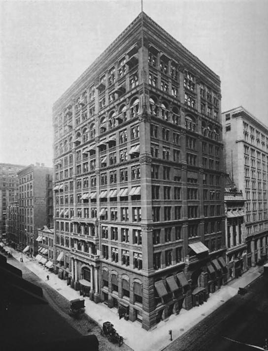
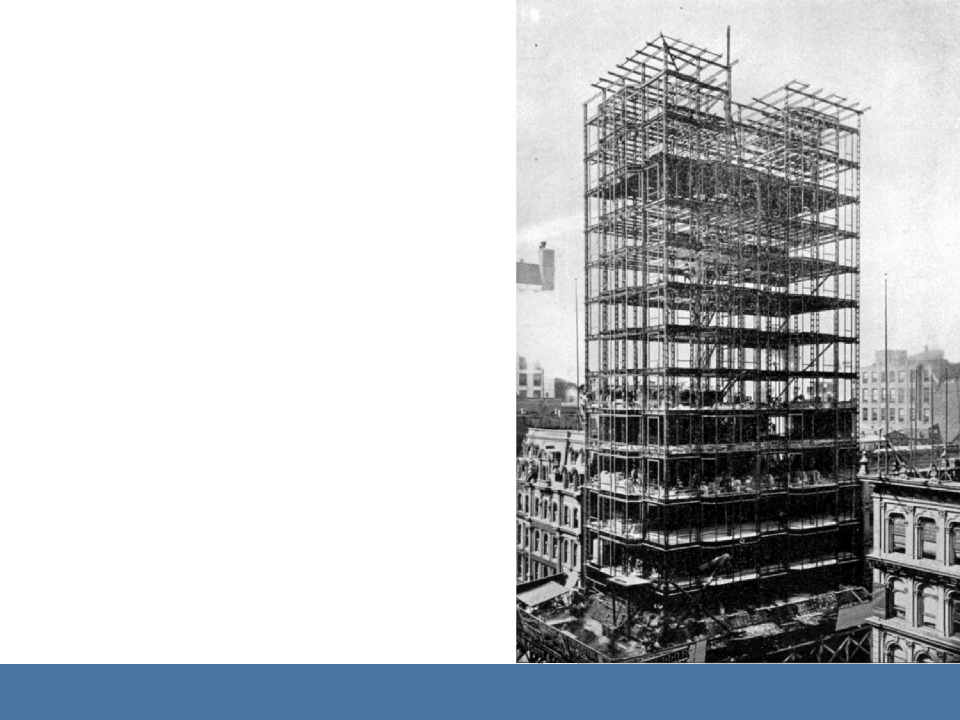
1850 and later
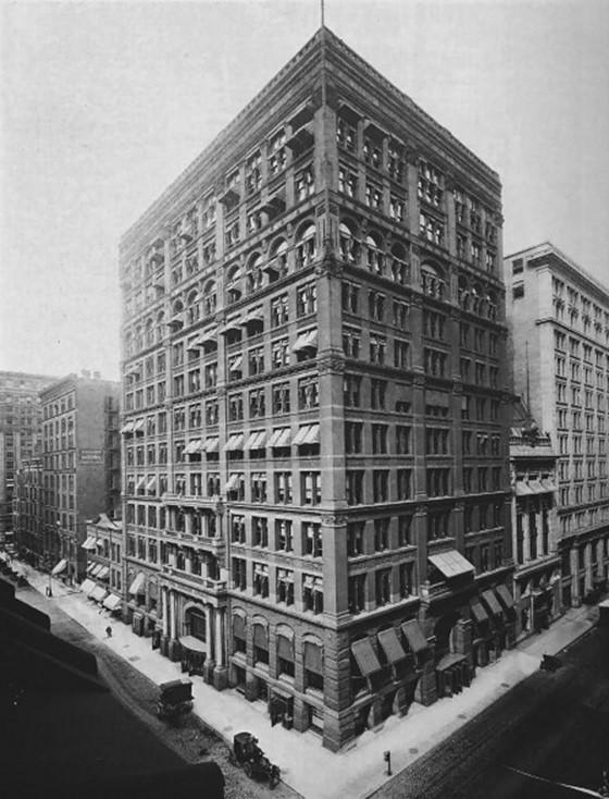
Right: Home Insurance Company Building, 1885, William Le Baron Jenny
First tall building supported entirely by a fire-protected metal frame (cast iron and steel)
Modern
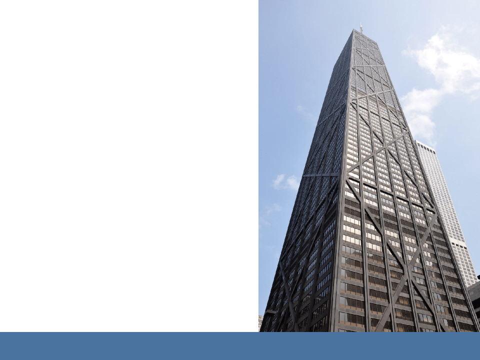
Steel is one of three commonly used noncombustible structural materials. Suitable for buildings of all sizes, from single family residences to the tallest skyscrapers.
Fundamentals of Building Construction, Materials & Methods, 6th Edition
Copyright © 2013 J. Iano. All rights reserved.
CONSTRUCTION
THE MATERIAL STELL
Fundamentals of Building Construction, Materials & Methods, 6th Edition
Copyright © 2013 J. Iano. All rights reserved.
Carbon Content in Iron Alloys
Greater proportions of carbon generally increase the hardness and brittleness of the iron alloy.
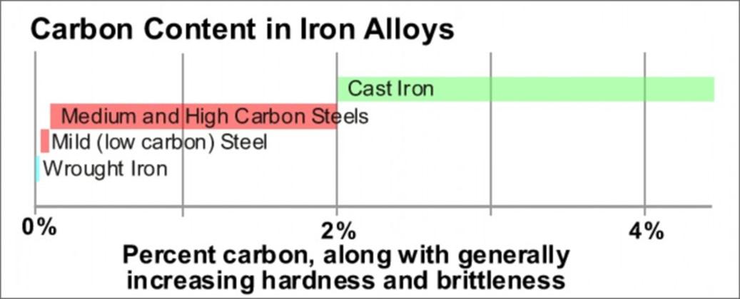
Cast Iron
2% – 4% carbon Strong in compression
Less strong in in tension
Brittle (vulnerable to sudden failure)
Fundamentals of Building Construction, Materials & Methods, 6th Edition
Copyright © 2013 J. Iano. All rights reserved.

Wrought Iron
Little or no carbon Strong in tension
Weaker in compression Malleable (easily
shaped) and
relatively soft
Fundamentals of Building Construction, Materials & Methods, 6th Edition
Copyright © 2013 J. Iano. All rights reserved.
Steel
Less than 2% carbon
Strong in both tension and compression
Ductile (not prone to sudden failure)
(Reliance Building, Chicago, 1895)
Fundamentals of Building Construction, Materials & Methods, 6th Edition
Copyright © 2013 J.
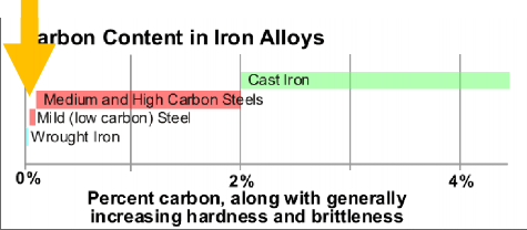
Mild Steel (Low carbon steel)
Most common alloy for modern structural steel
Not more than 0.3% carbon
Small amounts of other metals improve strength, toughness, and other qualities
Fundamentals of Building Construction, Materials & Methods, 6th Edition
Copyright © 2013 J. Iano. All rights reserved.
Reasonably strong, highly ductile, and easily welded
Equally strong in tension and compression
Fundamentals of Building Construction, Materials & Methods, 6th Edition
Copyright © 2013 J. Iano. All rights reserved.
Making Cast Iron
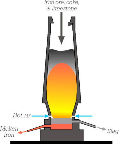
Iron ore (oxides of iron extracted from the ground) is combined with coke (carbon derived from coal) and limestone in a large blast furnace.
Hot air forced through the furnace burns the coke.
Chemical reactions with the combustion products remove oxygen from the ore, leaving elemental iron, but with a relatively high carbon content.
The limestone combines with impurities and is drawn off as waste slag.
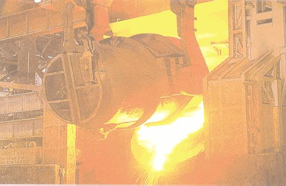
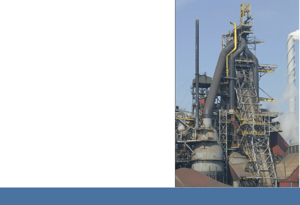
Steelmaking
In a traditional steel mill, iron ore is the raw
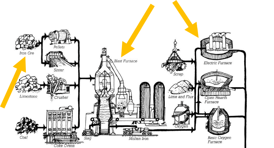
ingredient. First, it is processed into molten iron in a blast furnace, followed by conversion to steel in a second operation.
Fundamentals of Building Construction, Materials & Methods, 6th Edition
Copyright © 2013 J. Iano. All rights reserved.
Traditional Mills
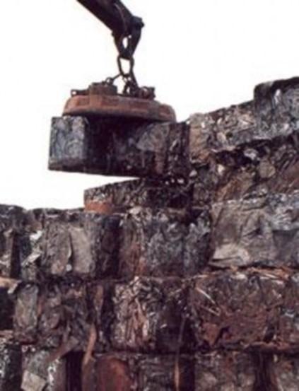
Recycled content: 25% – 35%
Casting
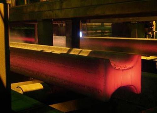
As the molten steel begins to solidify, it is cast into shapes ranging from plain rectangles or rounds to more complex cross sections, such as beam blanks (right), that approximate the shape of finished beam products.
Fundamentals of Building Construction, Materials & Methods, 6th Edition
Copyright © 2013 J. Iano. All rights reserved.
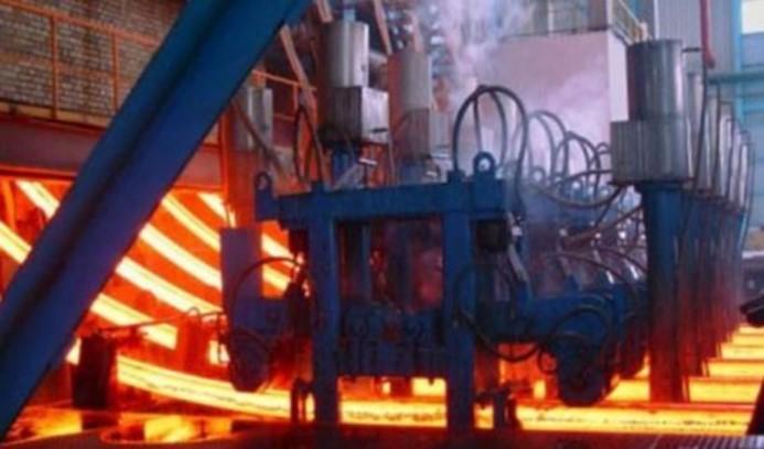
In the continuous casting process, casting begins once the outer shell of the steel mass has solidified, while the inner portion is still molten.
Fundamentals of Building Construction, Materials & Methods, 6th Edition
Copyright © 2013 J. Iano. All rights reserved.

Rolling Mill
Structural shapes are produced in a rolling mill. Prior to rolling, the beam blanks are reheated to the necessary temperature.
Fundamentals of Building Construction, Materials & Methods, 6th Edition
Copyright © 2013 J. Iano. All rights reserved.
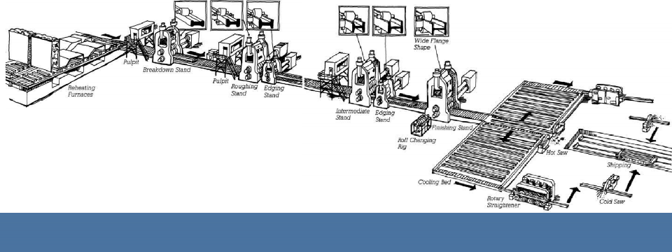
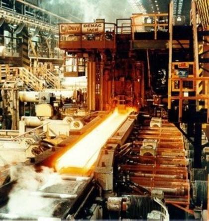
Rolling Mill
Blanks pass through a series of rollers and are progressively deformed into the desired final shape.
Fundamentals of Building Construction, Materials & Methods, 6th Edition
Copyright © 2013 J. Iano. All rights reserved
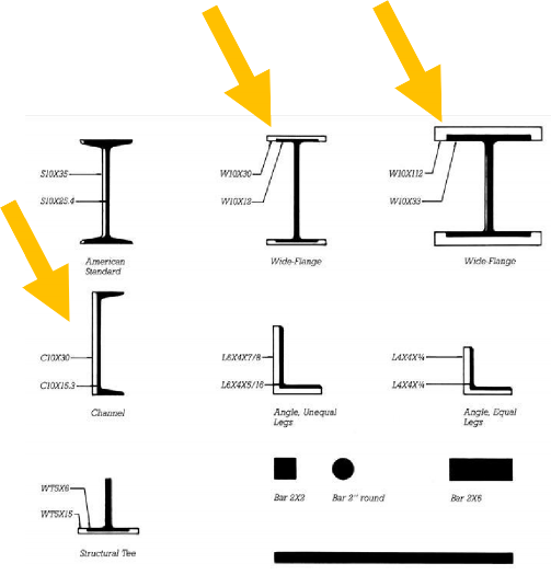
Structural Shapes
Wide-Flange
(W-Shape): The most commonly used shape for beams and columns
Not an I-beam!
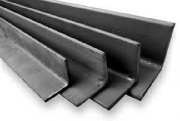
Channels, angles, tees: For trusses, lighter weight framing, and other miscellaneous uses
Fundamentals of Building Construction, Materials & Methods, 6th Edition
Copyright © 2013 J. Iano. All rights reserved.
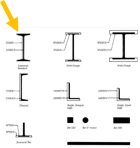
American Standard: Traditional I-beam with a shape that is less structurally efficient than a contemporary wide- flange of the same weight
Fundamentals of Building Construction, Materials & Methods, 6th Edition
Copyright © 2013 J. Iano. All rights reserved.
Shape Designation

W10 x 30
W: Wide-flange shape
10: Nominally 10 inches deep
30: 30 pounds per lineal foot
Fundamentals of Building Construction, Materials & Methods, 6th Edition
Copyright © 2013 J. Iano. All rights reserved

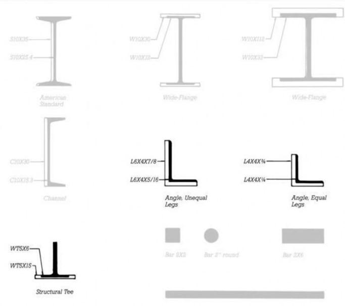
By varying roller sizes and spacings, various weights can be produced, all nominally 10″ in depth:
W10 x 12: 3.96″wide x 9.87″deep W10 x 30: 5.81″w x 10.5″d
W10 x 39: 7.99″w x 9.92″d
W10 x 112: 10.4″w x 11.4″d
Fundamentals of Building Construction, Materials & Methods, 6th Edition
Copyright © 2013 J. Iano. All rights reserved.
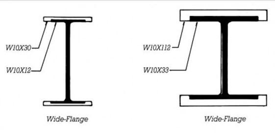
The unshaded portions of the diagrams illustrate how a variety of weights of beams can be rolled from the same set of rollers by opening up the space between the rollers.
Wide Flange Shapes
Taller more narrow profiles are best for horizontally spanning elements such as beams and girders.
Fundamentals of Building Construction, Materials & Methods, 6th Edition
Copyright © 2013 J. Iano. All rights reserved.
Profiles more square in proportion are better suited for use as vertical columns.
Fundamentals of Building Construction, Materials & Methods, 6th Edition
Copyright © 2013 J. Iano. All rights reserved.
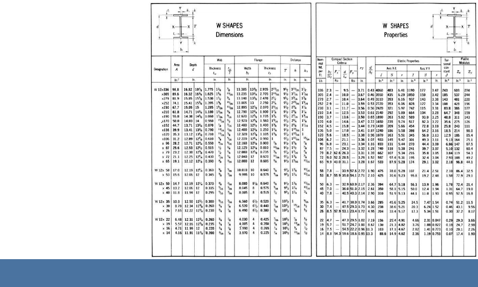
AISC Steel Construction Manual
Left page: Dimensional data
Right page:
Shape properties related to structural stiffness and strength calculations
Fundamentals of Building Construction, Materials & Methods, 6th Edition
Copyright © 2013 J. Iano. All rights reserved.
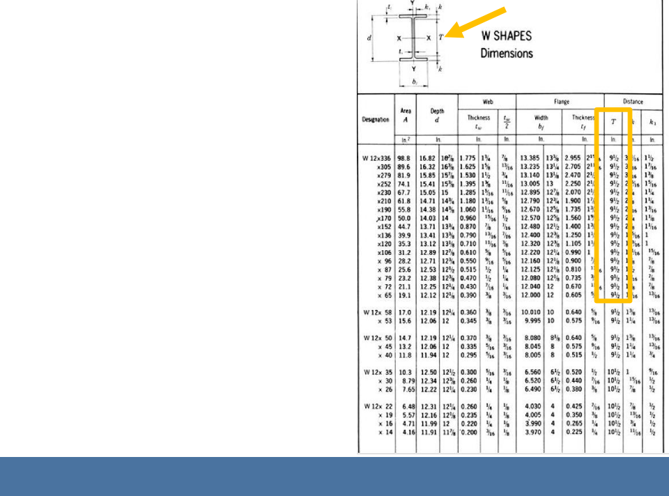
Within groups of shapes, T, the depth in-between top and bottom flanges, does not vary.
These shapes are
rolled from the same sets of rollers, with only the spacings of the rollers changing.
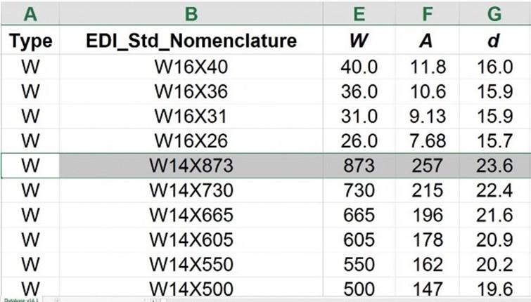
Size designations are nominal, not always an accurate indication of actual depth.
A W14 x 873 is 23.6″ deep!
Fundamentals of Building Construction, Materials & Methods, 6th Edition
Copyright © 2013 J.
Other Shape Designations
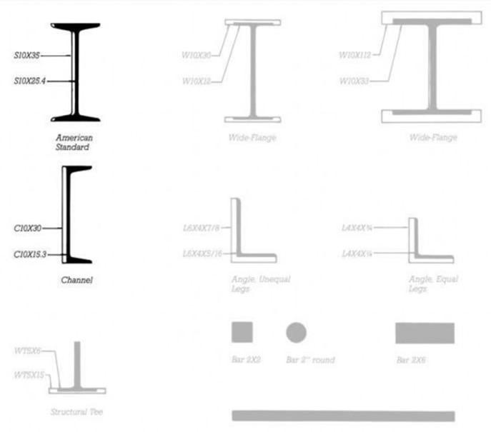
S: American Standard beam (“I-beam”)
MC:
Miscellaneous channel
C: American Standard channel
Fundamentals of Building Construction, Materials & Methods, 6th Edition
Copyright © 2013 J. Iano. All rights reserved.
L: Angle L4x3x3/8: 4″x3″ nominal
legs with 3/8″
thickness
Fundamentals of Building Construction, Materials & Methods, 6th Edition
Copyright © 2013 J. Iano. All rights reserved.

WT: T-shape cut from a W-shape WT13.5×47:
13.5″d x 47lb/ft.
(Produced by cutting a W27x94 lengthwise in half.)
Fundamentals of Building Construction, Materials & Methods, 6th Edition
Copyright © 2013
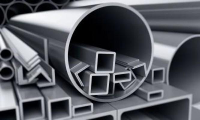
Hollow Structural Sections (HSS)

Hollow square, rectangular, round, and elliptical shapes
Made by cold- or hot- forming steel strip (sheet) and welding longitudinally
Fundamentals of Building Construction, Materials & Methods, 6th Edition
Copyright © 2013 J. Iano. All rights reserved.
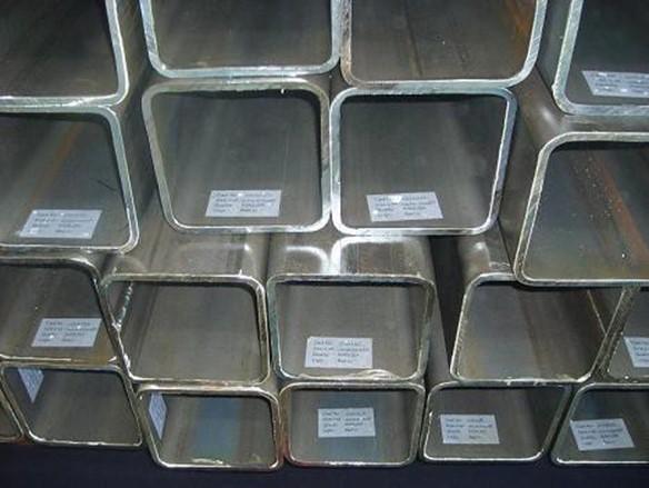
HSS shapes are used for trusses, structurally efficient column sections, and where the simple external profile is desirable.
Example designation: HSS 8 x 8 x ½ 8″x8″x½” wall thickness
Fundamentals of Building Construction, Materials & Methods, 6th Edition
Copyright ©
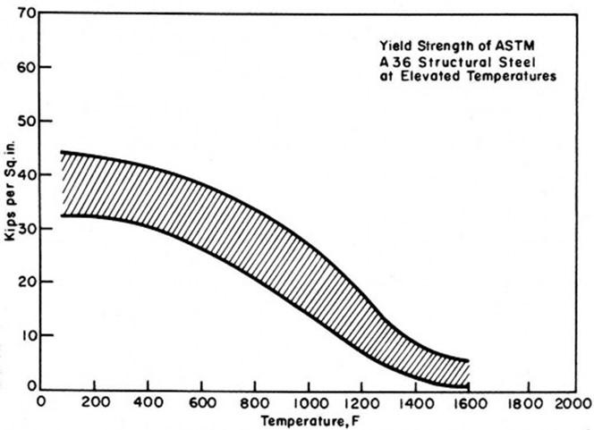
ASTM A36 Mild Steel
Traditional structural steel Minimum 36,000 lb
per sq. in. (36 ksi)
yield strength Now used mainly for accessory steel
angles, channels,
etc.
Fundamentals of Building Construction, Materials & Methods, 6th Edition
Copyright © 2013 J. Iano. All rights reserved.
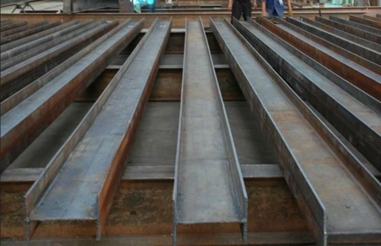
High-Strength, Low Allow Steels
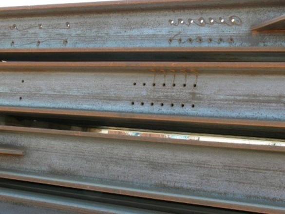
ASTM A992: W
shapes
ASTM A572: other shapes
Produced economically in mini-
mills from scrap steel
Minimum yield strength 50 to 65 ksi
ASTM A992 steel columns lay stacked in a fabricator yard. Note the holes predrilled for connections that will be completed in the field.
Fundamentals of Building Construction, Materials & Methods, 6th Edition
Copyright © 2013 J. Iano. All rights reserved.
High-Strength, Low Allow Steels
Use of stronger steel alloys permits savings in weight and reductions in the size of structural elements, reducing
costs. With controlled, thermal treatments applied after the shapes are formed, structural alloys with yield strengths greater than 100 ksi are produced.
Fundamentals of Building Construction, Materials & Methods, 6th Edition
Copyright © 2013 J. Iano. All rights reserved.
Weathering Steel
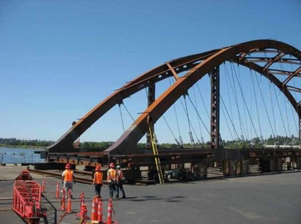
Surface oxidation adheres to base metal, limiting further rusting
Mostly used in highway and bridge structures,
eliminating the need for a protective coating.
(Often called Cor-Ten steel, a US
Steel trade name. )
Fundamentals of Building Construction, Materials & Methods, 6th Edition
Copyright © 2013 J. Iano. All rights reserved.
Stainless Steel
Added nickel and chromium Forms self-
protecting oxide
layer that provides long lasting protection against corrosion
Fundamentals of Construction, Materials & Methods, 6th Edition
Copyright © 2013 J. Iano.
Building
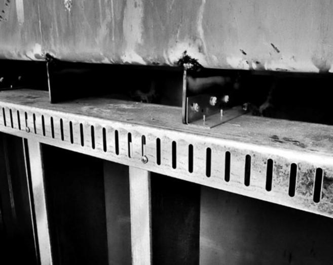
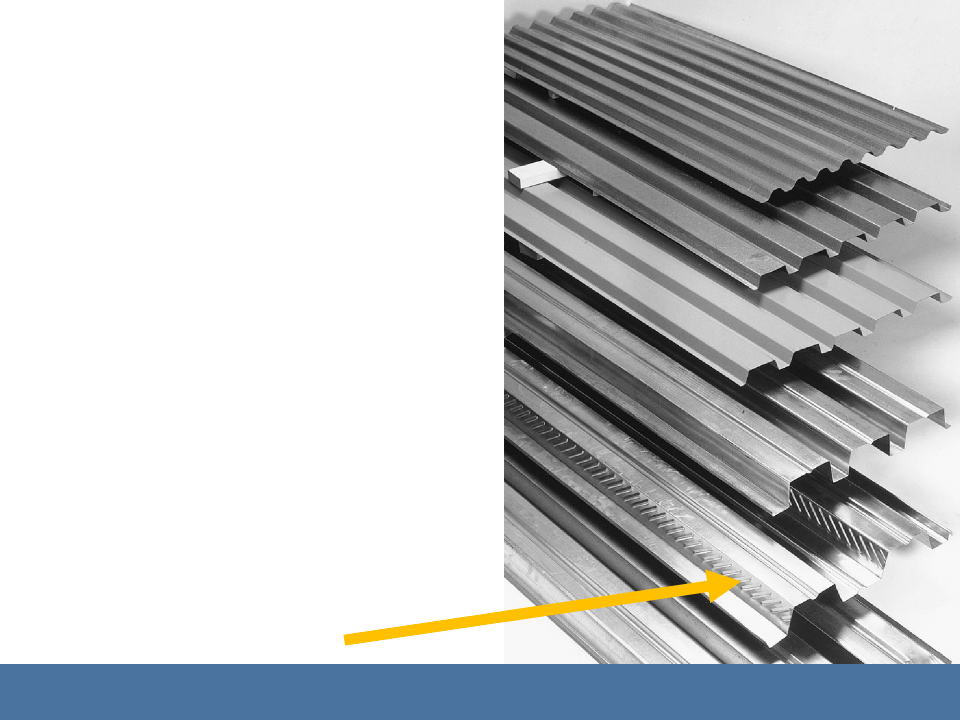
Cold-Formed Steel
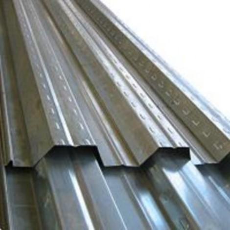
Deforming steel in its cold state causes realignment of the steel crystals and increases its strength.
Corrugated steel decking (right)
Steel studs and joists (Chapter 12)
High-strength wire for concrete prestressing strands (Chapter 13)
11 STEEL FRAME CONSTRUCTION
JOINING STEEL MEMBERS
Fundamentals of Building Construction, Materials & Methods, 6th Edition
Copyright © 2013 J. Iano. All rights reserved.
Fundamentals of Building Construction, Materials & Methods, 6th Edition
Copyright © 2013 J. Iano. All rights reserved.
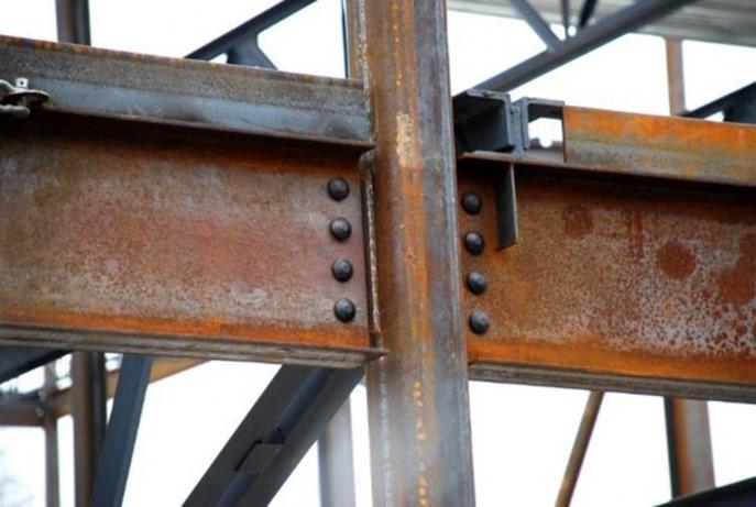
Riveting
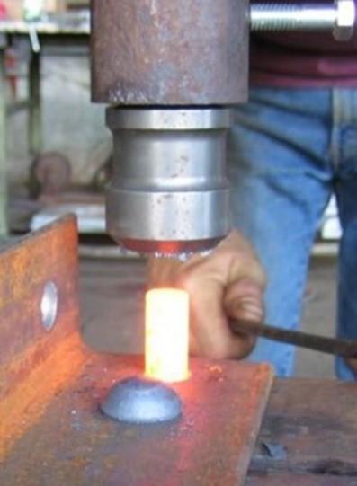
White-hot fastener is inserted through holes in members to be fastened.
Fastener is hammered to produce a head on the plain end.
Fundamentals of Building Construction, Materials & Methods, 6th Edition
Copyright © 2013 J. Iano. All rights reserved.
Joining Steel Members
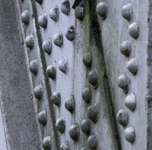
As the metal cools, it contracts, and tightly clamps the steel members.
Mostly found in historic structures. Rarely used in modern construction.
Fundamentals of Building Construction, Materials & Methods, 6th Edition
Copyright © 2013 J. Iano. All rights reserved.
Joining Steel Members
Bolting
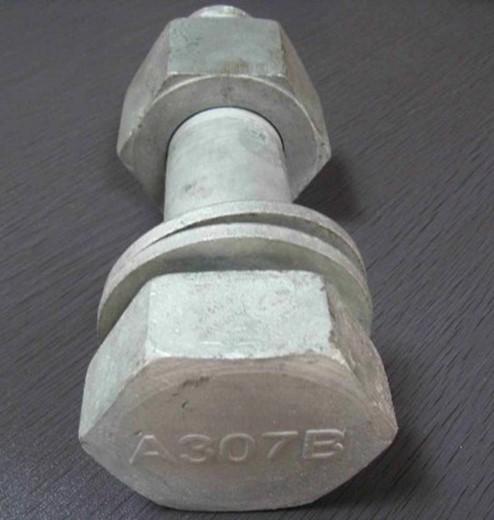
Carbon steel bolts
- Relatively low strength
- Limited uses, such as fastening light framing elements or holding temporary connections
-
Also called common, or unfinished bolts
Fundamentals of Building Construction, Materials & Methods, 6th Edition
Copyright © 2013 J. Iano. All rights reserved.
Joining Steel Members
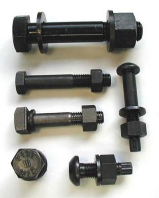
High-strength bolts
- Stronger than common bolts
-
Used for fastening primary structural members
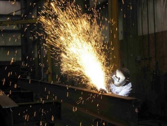
Joining Steel Members
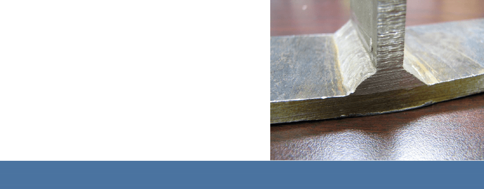
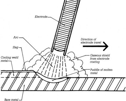
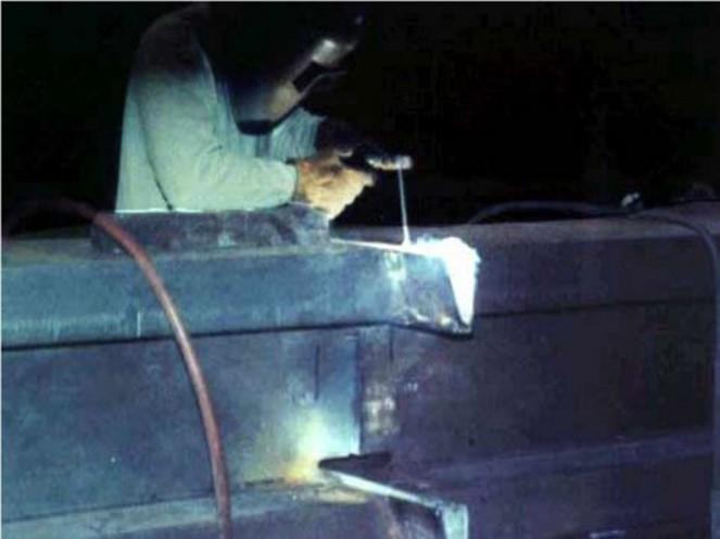
Welding
Steel surfaces to be joined are heated to a molten state.
Additional molten metal is added from the electrode.
In finished joint, members are fully fused.
Fundamentals of Building Construction, Materials & Methods, 6th Edition
Copyright © 2013 J. Iano. All rights reserved.
11 STEEL FRAME CONSTRUCTION
DETAILS OF
STEEL FRAMING
Fundamentals of Building Construction, Materials & Methods, 6th Edition
Copyright © 2013 J. Iano. All rights reserved.
Fundamentals of Building Construction, Materials & Methods, 6th Edition
Copyright © 2013 J. Iano. All rights reserved.
Details of Steel Framing
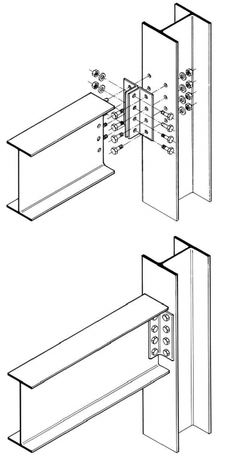
Framed Connection
Angles, plates, or tees connect web of beam to side of column.
Angles are usually joined to beam in the fabricator’s shop.
Beam/angle assembly is bolted to the column in the field.
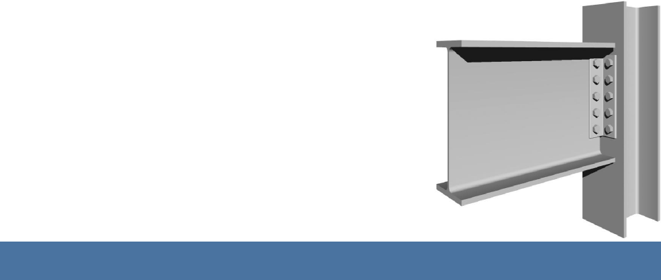
Details of Steel Framing
Shear Connection
Transfers gravity loads from beam to columns. Not sufficiently rigid to
transfer bending forces.
Modeled structurally as if it is free to rotate, or hinged.
AISC Simple Connection
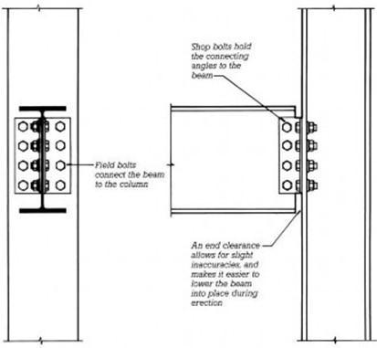
Details of Steel Framing
Shear tabs welded to column in shop, bolted to beam in the field.
Beams cut short to allow for deviations in column positions and to ease installation.
Details of Steel Framing
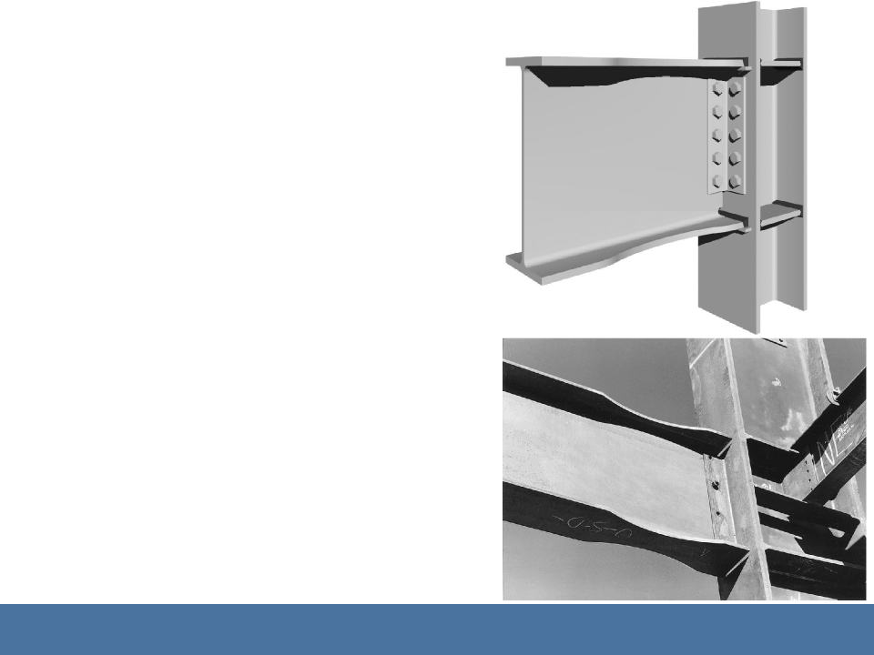
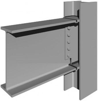
Moment Connection
Transfers gravity loads and bending forces.
Beam flanges are joined to column.
Column is reinforced to carry bending forces.
Beam is restrained from even small rotations.
AISC Fully Restrained
Fundamentals of Building Construction, Materials &
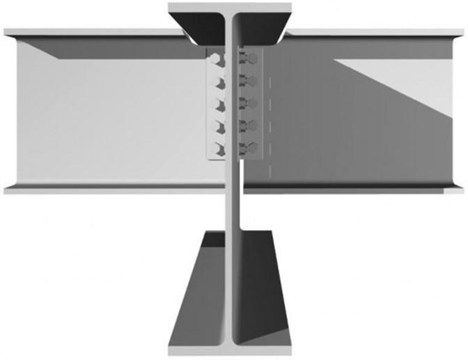
Details of Steel Framing
“Dog bone” cut creates a zone of weakness.
In extreme seismic event, this area will deform plastically, protecting the more brittle welds from failure.
Single common bolt holds beam temporarily prior to welding.
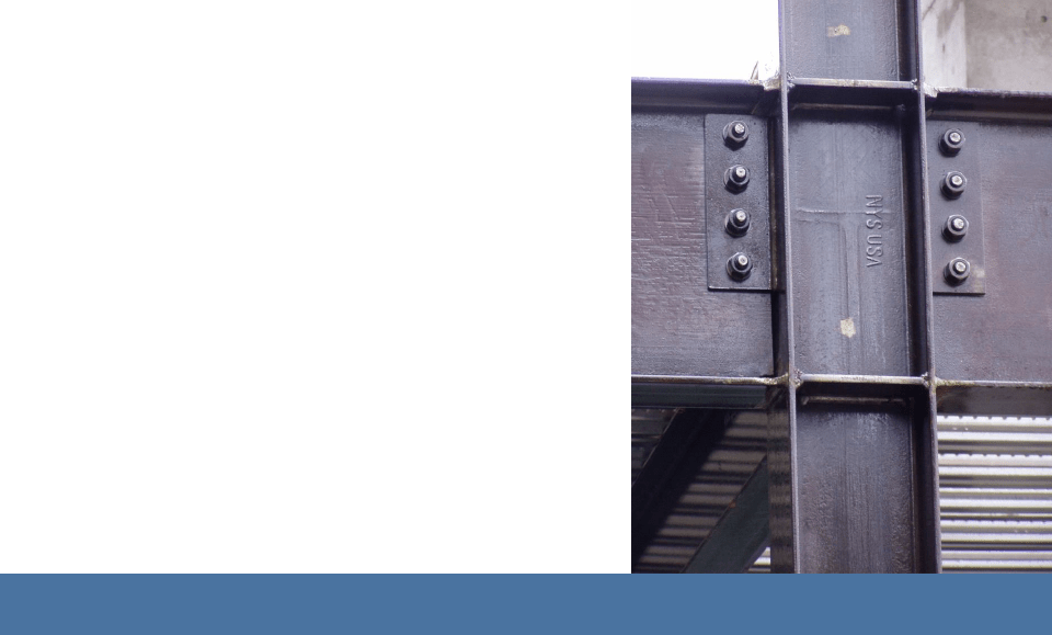
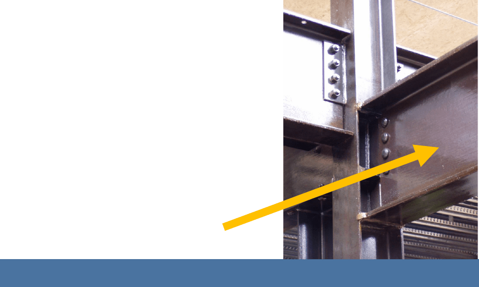
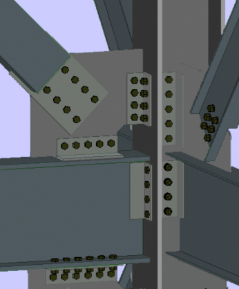
Details of Steel Framing
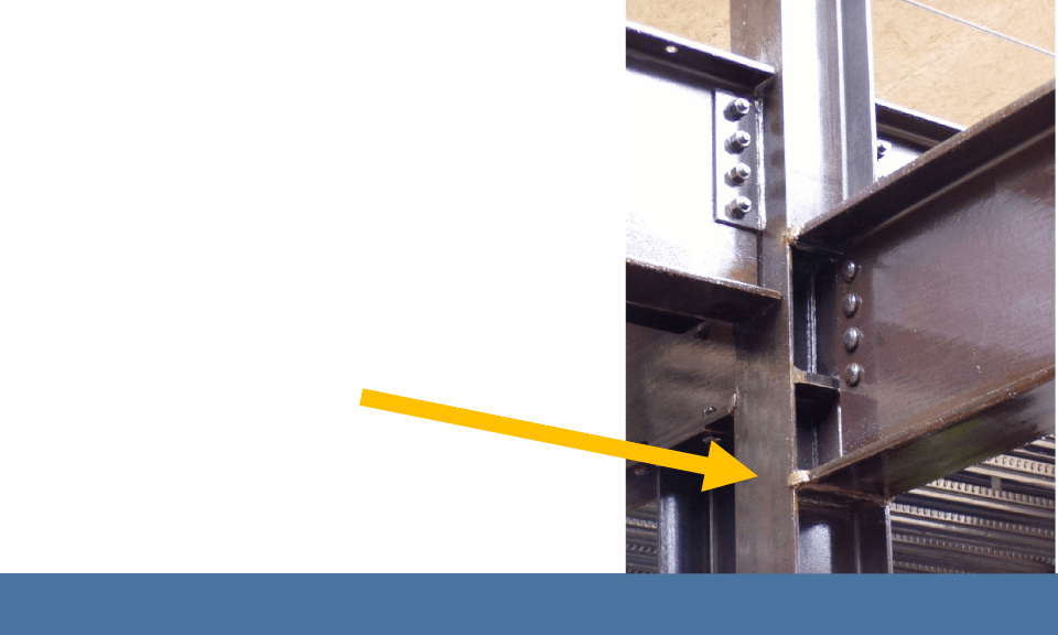
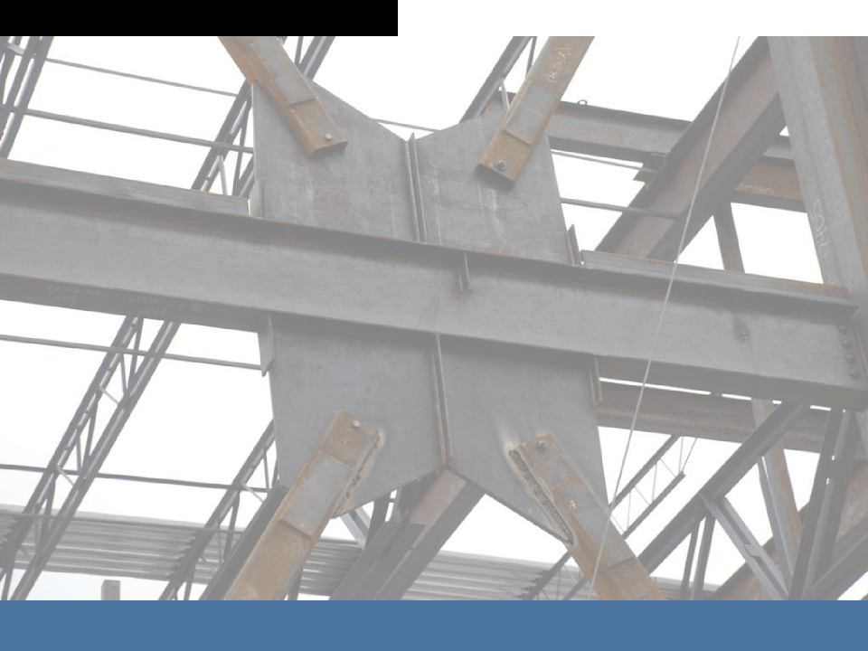
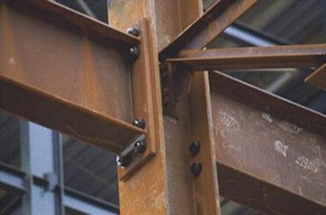
A pair of beam-column moment connections.
Full penetration welds join top and bottom beam flanges to column and column reinforcing plates.
Fundamentals of Building Construction, Materials & Methods, 6th Edition
Copyright © 2013 J. Iano. All rights reserved.
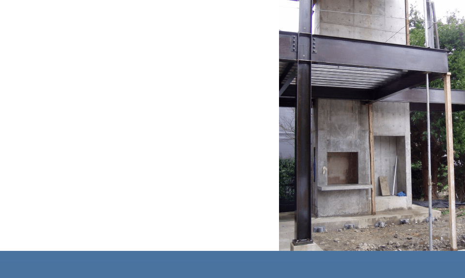
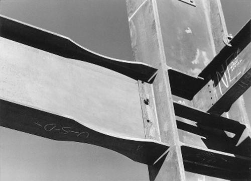
Details of Steel Framing
This connection creates a continuous beam condition that can fully transmit bending forces, allowing the cantilever on the right.
A shear connection would not work here. (Posts at corner are temporary.)
Fundamentals of Building Construction, Materials & Methods, 6th Edition
Copyright © 2013 J. Iano. All rights reserved.
Details of Steel Framing
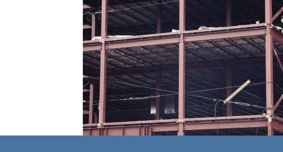
Stabilizing the Building Frame
Rectangular geometry of the building frame must be made stable against lateral forces by:
- Diagonal bracing
- Moment-resisting frame
-
Shear walls
Fundamentals of Building Construction, Materials & Methods, 6th Edition
Copyright © 2013 J. Iano. All rights reserved.

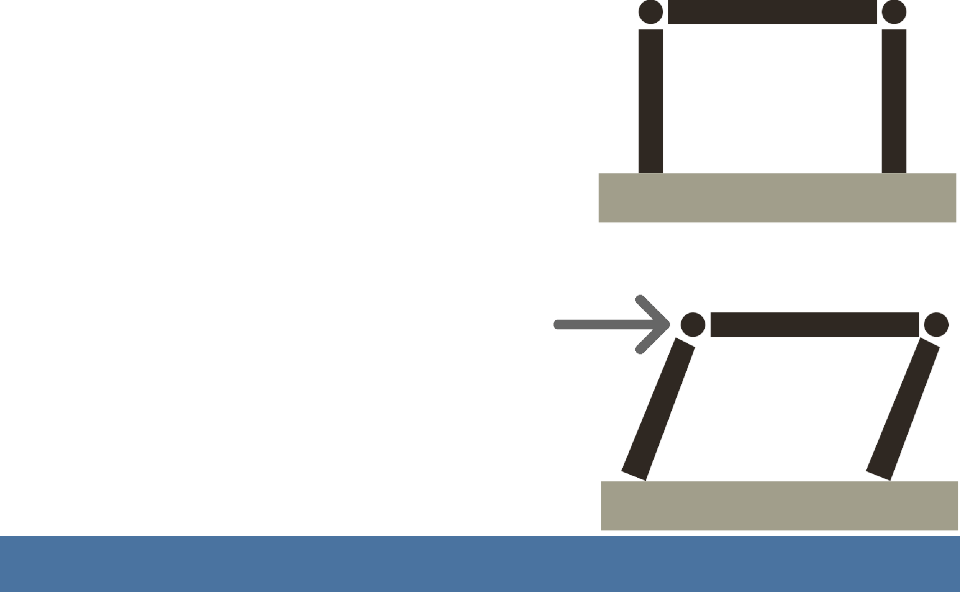
Details of Steel Framing
Braced Frame
Diagonal bracing creates stable, triangular geometry.
Can be constructed with shear connections between beams and columns (free to rotate).
Fundamentals of Building Construction, Materials & Methods, 6th Edition
Copyright © 2013 J. Iano. All rights reserved.
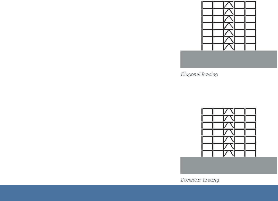
Details of Steel Framing
Eccentric bracing (bottom) allows a plastic hinge conditions to develop during extreme seismic events, absorbing the dynamic energy of the earthquake. (Same strategy as the dog bone.)
Fundamentals of Building Construction, Materials & Methods,
Details of Steel Framing
Moment-Resisting Frame
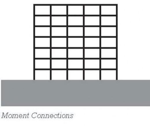
Moment-Resisting Frame
Some or all of the beam-column connections are moment connections capable of resisting rotations between the members, making the frame stable.
Fundamentals of Building Construction, Materials & Methods, 6th Edition
Copyright © 2013 J. Iano. All rights reserved.
Details of Steel Framing
Shear Walls
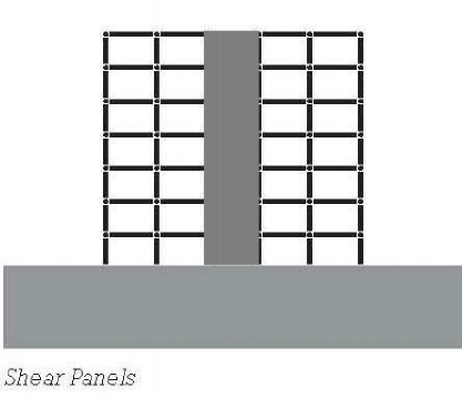
Shear Walls
Rigid vertical walls or core structures resist lateral forces.
Remainder of frame relies on shear connections.
Usually concrete. Occasionally heavy steel plate.
Fundamentals of Building Construction, Materials & Methods, 6th Edition
Copyright © 2013 J. Iano. All rights reserved.

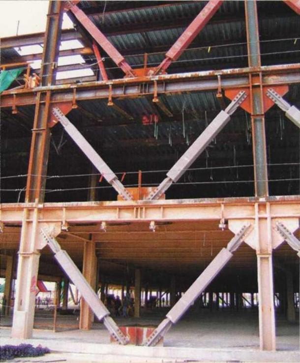
Details of Steel Framing
Methods can also be combined: Inverted vee
bracing with
beam-to-column fully-restrained moment connections.
Fundamentals of Building Construction, Materials & Methods, 6th Edition
Copyright © 2013 J. Iano. All rights reserved.
- Stronger than common bolts
Details of Steel Framing
These are buckling-resistant braces, designed to deform plastically in a controlled manner and absorb seismic energy during an earthquake.
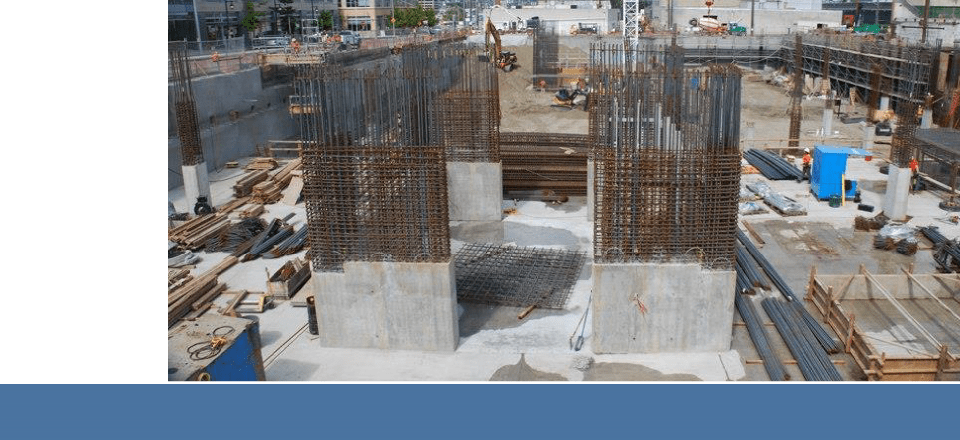
Details of Steel Framing
Beginnings of a heavily reinforced concrete core that will contain vertical services and act as stabilizing shear walls.
Lateral forces are greatest at the base of the building and diminish toward the top.
Fundamentals of Building Construction, Materials & Methods, 6
Details of Steel Framing
More Connections
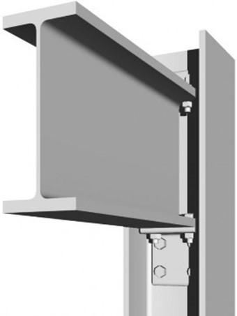
When connecting beam to column web, access is more constrained.
A seated connection relies on a seat angle below the beam and stabilizing angle at top.
AISC Simple Connection
Fundamentals of Building Construction, Materials &
Details of Steel Framing
Bolted web and welded flanges. The shear tab is deep enough to position the bolts clear of the column flanges for easy access.
AISC Fully-Restrained
Details of Steel Framing
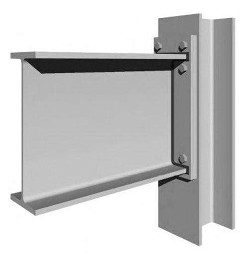
End plate is welded to the beam in the shop and bolted to the column in the field.
AISC Partially- Restrained, capable of transferring some but not all of the bending strength of the beam.
Fundamentals of Building Construction, Materials
Details of Steel Framing
Partial bending stress resistance is achieved, without welding in the field.
Fundamentals of Building Construction, Materials &
Details of Steel Framing
Framed beam- girder connection Beam top flanges
are coped, to
allow the tops of beam and girder to be set level.
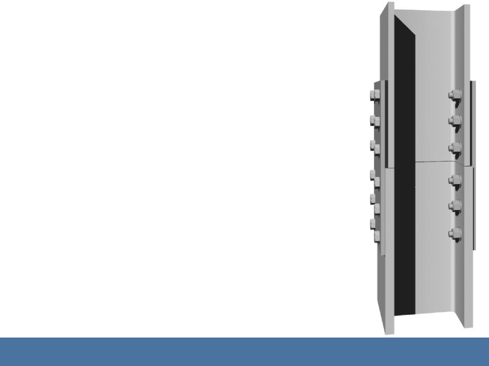
Details of Steel Framing
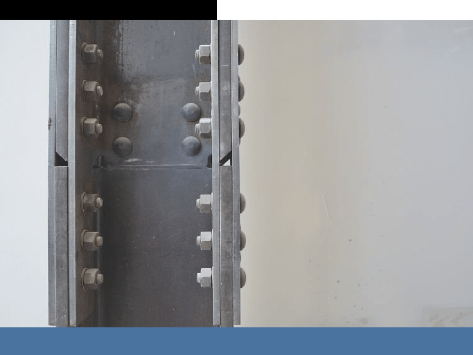
Bolted column or splice. Splices typically located at roughly waist height, to avoid interference with beam- column connections at floor and so that column splices are are conveniently accessible to workers standing on the floor deck.
Fundamentals of Building Construction, Materials & Methods, 6th Edition
Copyright © 2013 J. Iano. All rights reserved.
Details of Steel Framing
Where outer dimensions of connected column sections vary, shims or filler plates are inserted to make up the difference.
Fundamentals of Building Construction, Materials & Methods, 6th Edition
Copyright © 2013 J. Iano. All rights reserved.

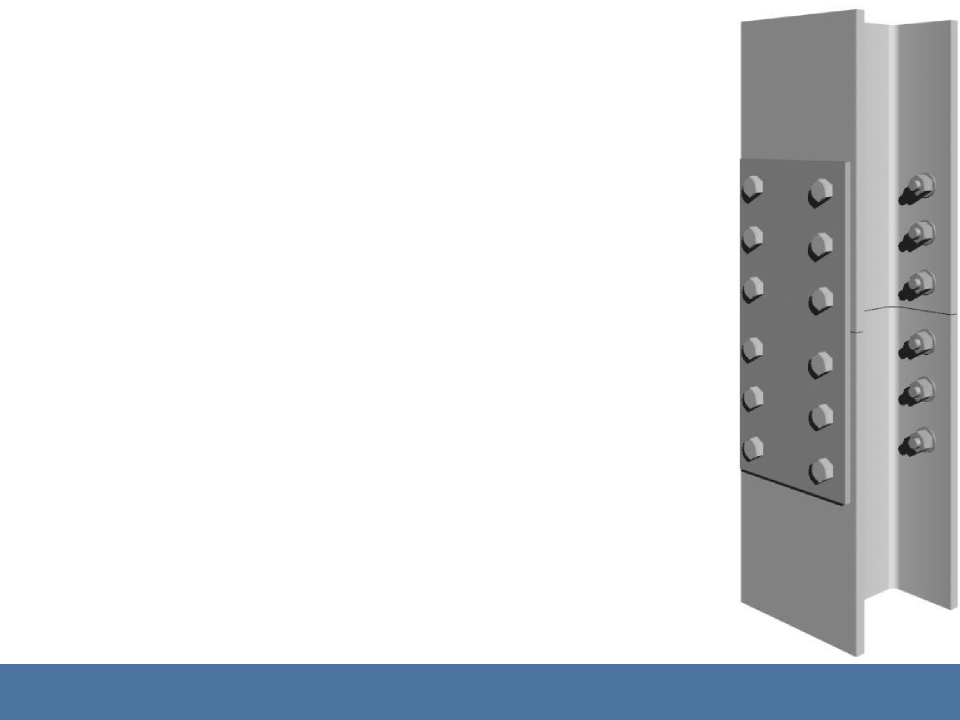
Details of Steel Framing
Welded column splice. The bolted connector plate holds the columns in alignment prior to welding. Later, the column flanges are welded with partial penetration welds. The hole in the plate provides an attachment point for the lifting line during erection.
Fundamentals of Building Construction, Materials & Methods, 6th Edition
Copyright © 2013 J. Iano. All rights reserved.

Details of Steel Framing
Where inner dimensions of spliced columns differ, a butt plate or bearing plate is added to the connection.
The plate is thick enough to transfer the full bearing loads from the upper column section to the lower one.
Fundamentals of Building Construction, Materials & Methods, 6th Edition
Copyright © 2013 J. Iano. All rights reserved.
11 STEEL FRAME CONSTRUCTION
THE CONSTRUCTION PROCESS
Fundamentals of Building Construction, Materials & Methods, 6th Edition
Copyright © 2013 J. Iano. All rights reserved.
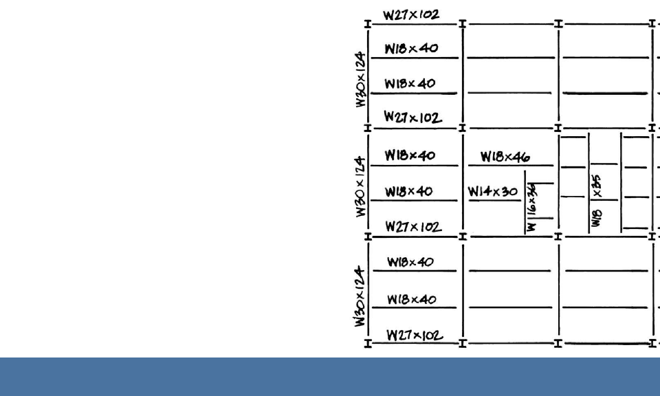
The Construction Process
Steel Framing Plan
Shows sizes and locations of steel members
(Dimensions have been omitted from the plan at right.)
Fundamentals of Building Construction, Materials & Methods, 6th Edition
Copyright © 2013 J. Iano. All rights reserved.
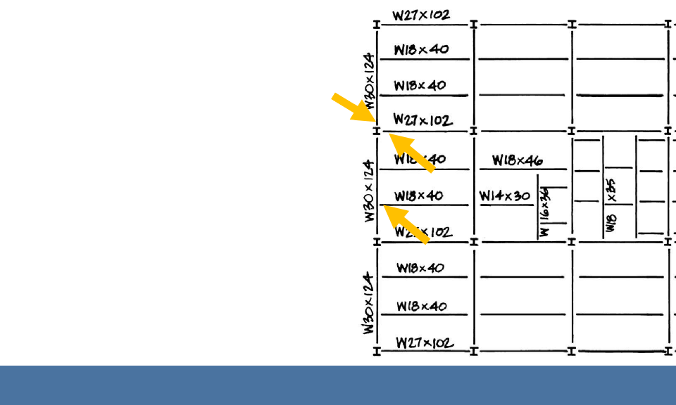
The Construction Process
Steel Framing Plan
W30 girder-column connection: Beam to column flange
W27 beam-column connection: Beam to column web
W18 to W30
connection: Coped beam-girder
The Construction Process
Steel Fabricator
Fabricator prepares steel members and delivers them to the construction site.
Fundamentals of Building Construction, Materials &
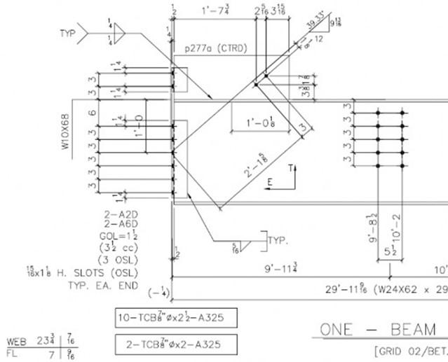
The Construction Process

Traditionally, the fabricator prepares shop drawings showing the configuration of each member.
Drawings are reviewed by architect and structural engineer.
Fundamentals of Building Construction, Materials &
The Construction Process
Fabricator frequently also shares responsibility for design of the steel connections, based on more general requirements provided by the structural engineer.
Fundamentals of Building Construction, Materials &
The Construction Proces
Workers cut to length, cope, drill, punch, weld, and add tabs, angles, plates and other accessories to members as indicated on the approved shop drawings.
Fundamentals of Building Construction, Materials &
The Construction Proces
Welding deep, full-penetration groove welds to join two heavy A913 steel column sections end-to-end.
The Construction Process
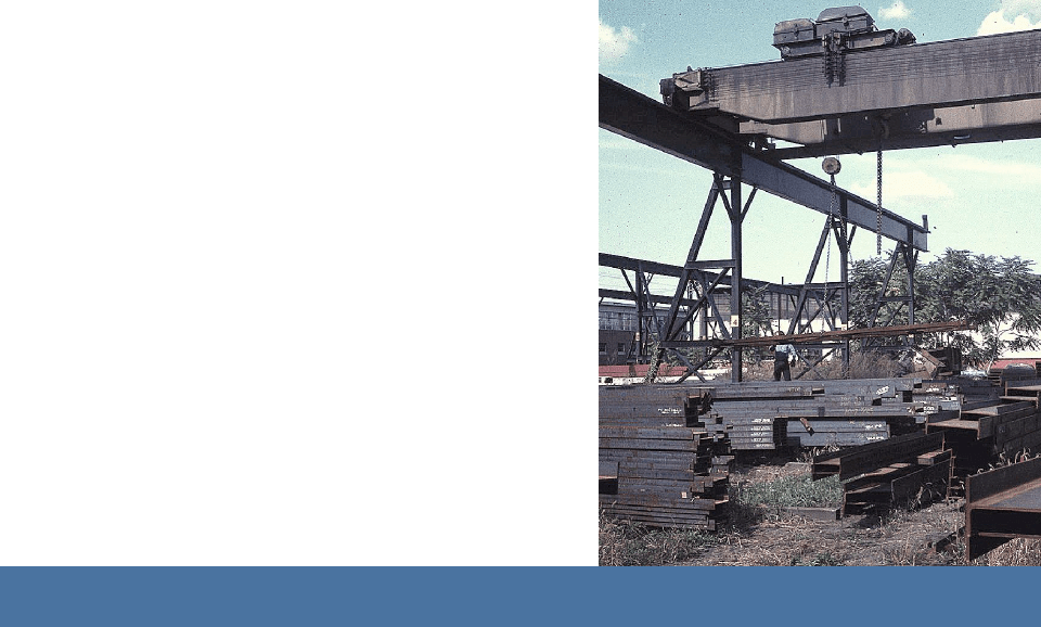
Fabricated members are stacked using overhead crane, awaiting transportation to the construction site.
Fundamentals of Building Construction, Materials & Methods,
The Construction Process
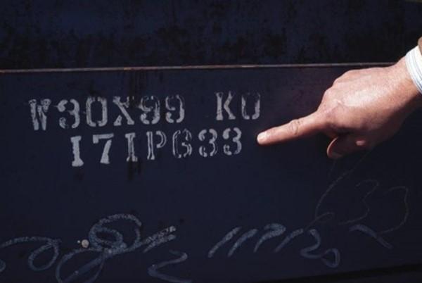
Members are individually labeled to correspond to information on the erection drawings so that each piece can be assembled in the proper location once delivered to the construction site.
Fundamentals of Building Construction, Materials & Methods, 6th
The Construction Process
More recently, using building information modeling systems, steel fabrication information and details may be developed by the structural engineer in the building model as an alternative to relying on fabricator shop drawings.
Fundamentals of Building Construction, Materials &
The Construction Process
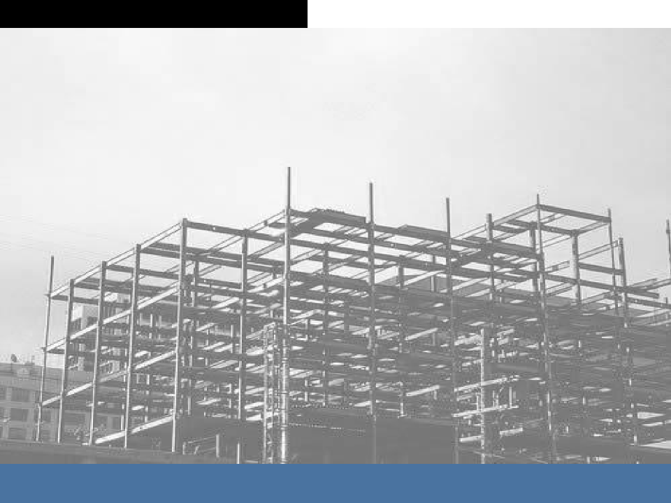
The Erector
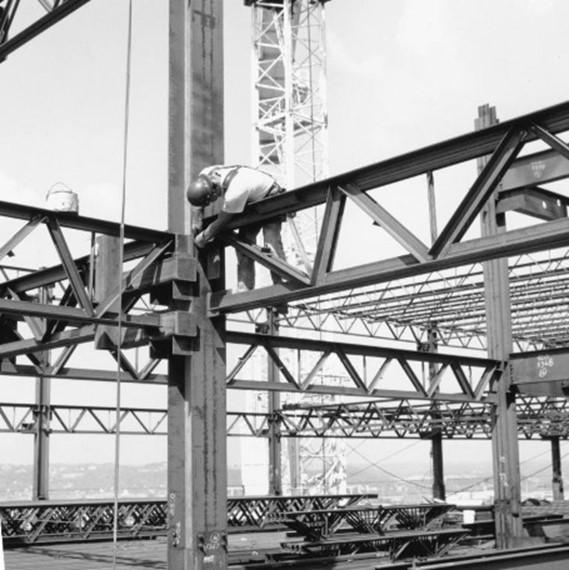
Assembles steel members delivered to the construction site.
May or may not be same entity as fabricator.
Workers are called ironworkers.
The Construction Process
As the frame is erected, temporary cables with turnbuckles are used to plumb up (make vertical) the frame.
The Construction Process
Steel Decking
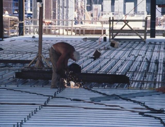
Corrugated steel decking laid over the framing is the most common floor and roof decking material.
The decking is puddle welded to the framing members below.
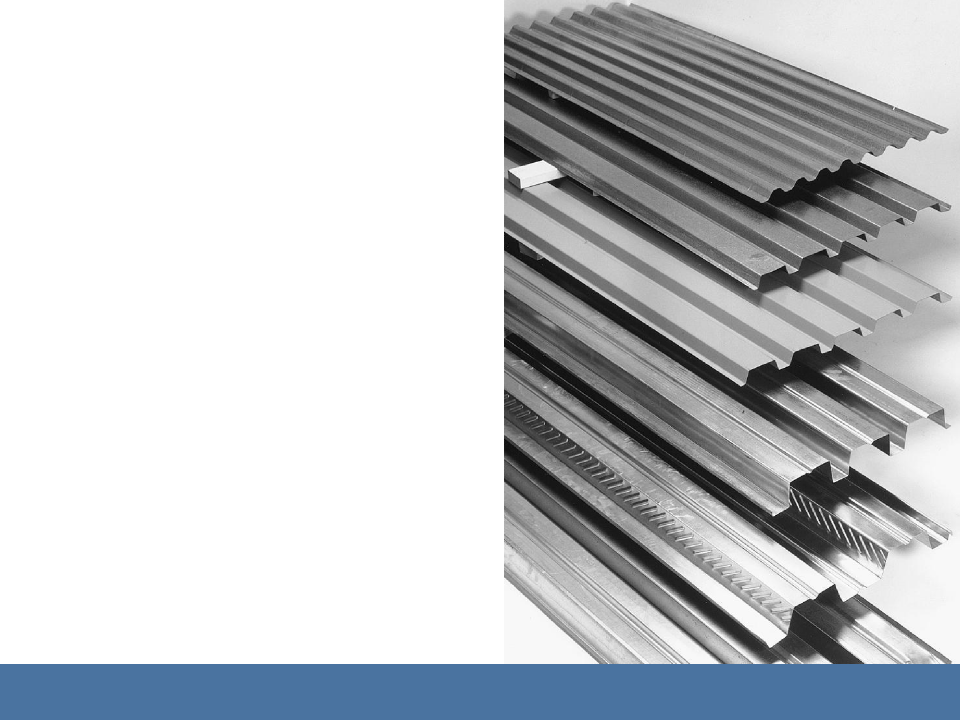
The Construction Process
Steel decking comes in a variety of profiles and depths to suit different load and span conditions.
Top: Relatively shallow roof decking.
Fundamentals of Building Construction, Materials & Methods, 6th Edition
Copyright © 2013 J. Iano. All rights reserved.
The Construction Process
Composite floor decking. Deformations allow structural bond between deck and concrete poured over it, to increase the strength of the deck/concrete floor assembly.
Copyright © 2013 J. Iano. All rights reserved.
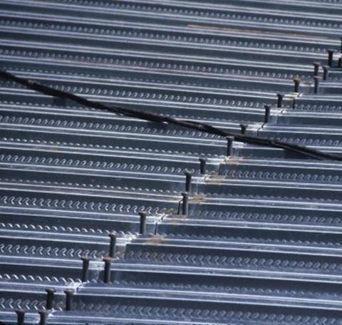
The Construction Process
Shear Studs
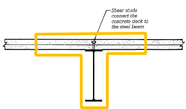
Welded to tops of beams, through metal decking. Once concrete is poured, the beams, decking, and concrete act together structurally as another form of composite construction.
Fundamentals of Building Construction, Materials & Methods,
The Construction Process
Concrete Fill
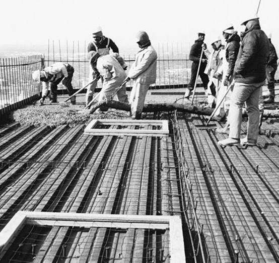
Concrete is placed over the metal decking to complete the structural floor or roof deck.
A grid of welded wire reinforcing within the concrete increases resistance to cracking.
Fundamentals of Building Construction, Materials &
The Construction Process
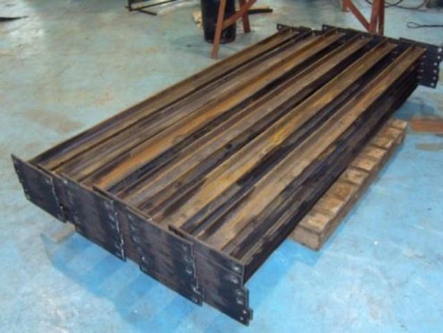
Other Decking Materials
Precast concrete planks placed over steel members (right).
Other lightweight board or plank materials may be used for roof decks.
11 STEEL FRAME CONSTRUCTION
FIRE PROTECTION OF STEEL FRAMING
Fundamentals of Building Construction, Materials & Methods,
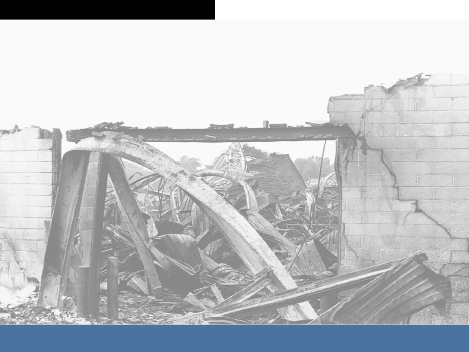
Fire Protection
Fireproofing
Above roughly 500 – 600
degrees F, steel rapidly looses strength.
Fireproofing acts as insulation, protecting steel from the heat of fire.
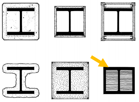
Fire Protection
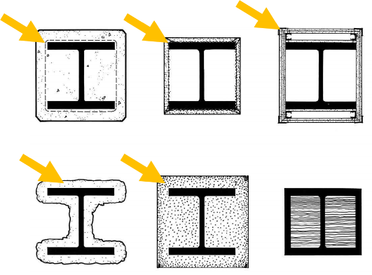
Concrete Plaster Gypsum Board
Gypsum wallboard Spray-applied insulation
Loose insulation within column cover
Fundamentals of Building Construction, Materials & Methods,
Fire Protection
US Steel Building, Pittsburg, used water- filled columns
Not shown:
-
Insulation blankets
:
- Intumescent Coatings Thin, coatings that expand to create a thicker, insulating layer when exposed to the heat of fire
Fundamentals of Building Construction, Materials
Fire Protection
Spray-Applied Fire-Resistive Material (SFRM)
Most common
To achieve an equal level of protection, lighter members require more insulation than heavier ones, since lighter members heat up more quickly.
Fundamentals of Building Construction, Materials & Methods, 6th Edition
Copyright © 2013 J. Iano. All rights reserved.
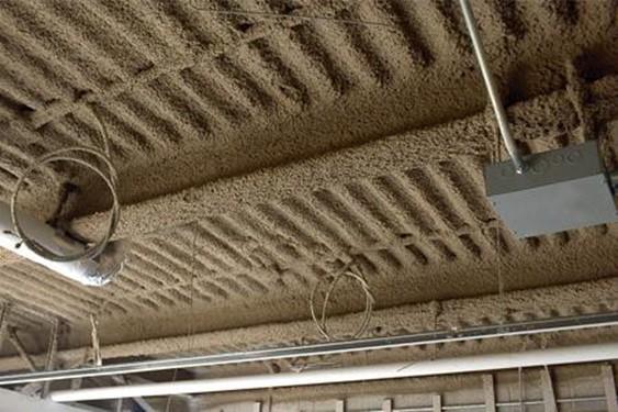
Fire Protection
Spray- applied fireproofing, in progress, applied to framing in a steel high rise structure.
Fundamentals of Building Construction, Materials & Methods,
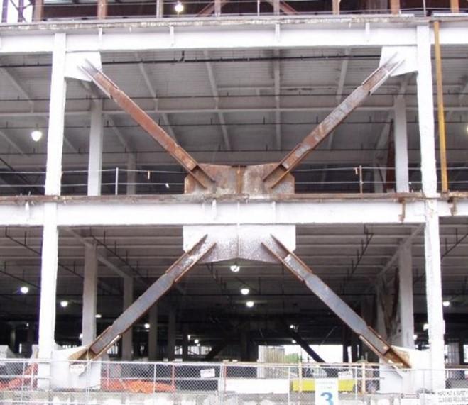
Bracing, which resists wind and earthquake—but not gravity— loads, is not required to be fire-protected.


