
BUILDING CONSTRUCTION
PRE-CONSTRUCTION SITE WORKS
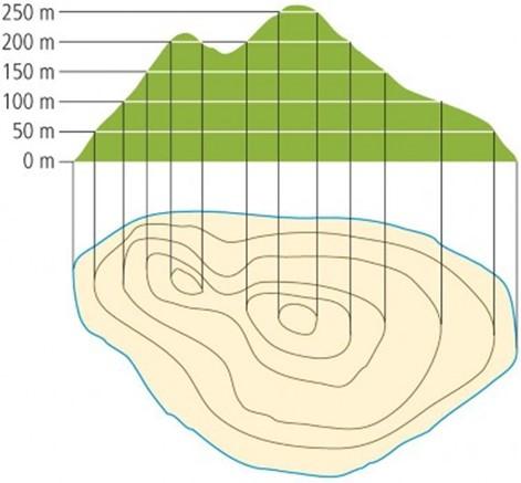
(1) SITE SURVEY
-
First of all site is surveyed and topographical details are drawn on the site plan. Plane table, Auto level and theodolite are used for this purpose.
-
Contouring is done by any suitable method of contouring and the contours are drawn on the site plan.
-
Following the contour map, site is leveled doing necessary cuttings and fillings with the help of any
suitable machinery.
(1) SITE SURVEY
- The datum level is set out.
- It is a level marked on the sections of the drawings, from which all heights and depths are marked in figures.
-
The datum is usually taken as the surface of the finished ground floor, abbreviated on the working drawing as F.F.L.
-
It is set out by a leveling instrument.
-
A peg is driven into the ground such that its top is at the F.F.L.
(1) SITE SURVEY
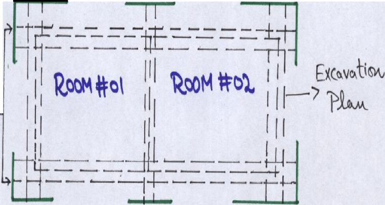
(5) The ground floor plan is marked on the ground.
-
First of all center lines of all walls are marked on the ground.

-
Right angles are taken by cross staff, optical square or more precisely, by a Theodolite.
- The lines showing the intended lines of
foundation trenches are marked by driving wooden pegs along these lines.
(2) PROFILE BOARDS
-
These are horizontal wooden boards fixed on edge, outside the foundation dig for a building.
-
The level at which these are fixed is usually basement or ground floor (or a convenient place).
I
(3) REMOVAL OF TOP SOIL
-
Before the foundation trenches are excavated, the surface vegetation, roots, plants, shrubs and usually all the top soil up to a depth of 150 mm to 300 mm will have to be removed, from the area of the site to be covered by the building.
-
This is done to ensure that the ground, upon which the structure is to be built, will be sterile (free from decomposable material i.e., organic material).
-
The removed top soil is valuable for subsequent use in the garden lay-out.
(4) SITE DRAINAGE
-
The building regulations also require that sub- soil of any site to be used for building must be effectively drained.
(5) EXCAVATION
-
When the setting out is completed and the profiles are in position, excavation of the trenches for the foundation is started.
(As per design requirements)
EXCAVATION
-
Machines: Hydraulic Diggers ,Tractor Shovel , Dumper
-
When soil has been tipped by the Digger, it can be lifted by the Tractor Shovel and put into the Dumper, to be carried away and discharged, where ever it is required for making up levels on the site.
-
While Excavation, Safety should never be ignored.

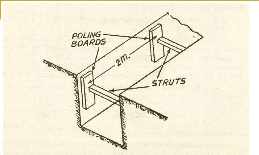
Timbering of trenches in Hard Soil
(With a central strut to each pair of Poling Boards)
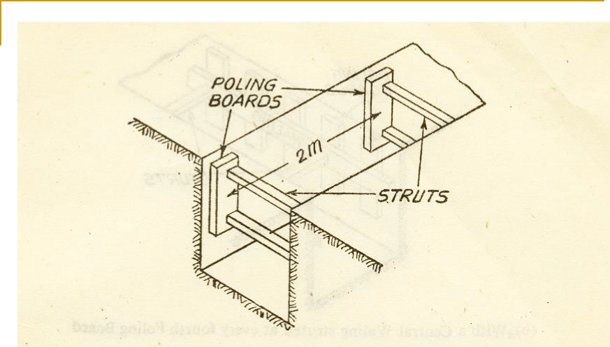
Timbering of trenches in Hard Soil
(With two struts to each pair of Poling Boards)
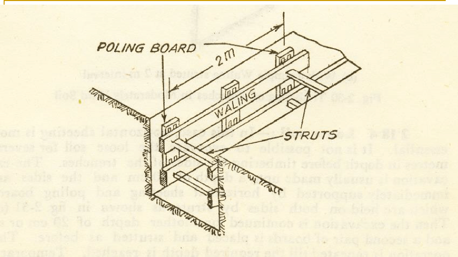
Timbering of trenches in Moderately Hard Soil
(With Walings strutted at alternate Poling Boards )
Timbering of trenches in Moderately Hard Soil
(With a central Waling strutted at every fourth Poling Board)
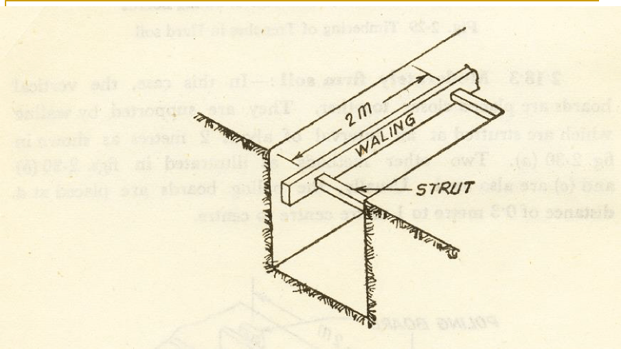
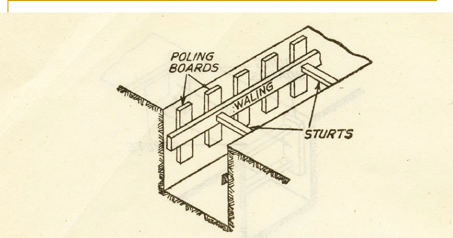
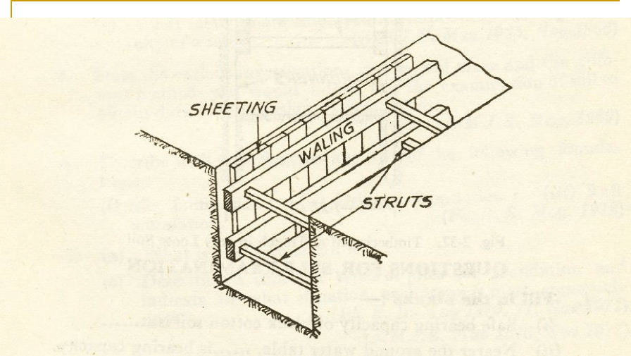
Timbering of trenches in Moderately Hard Soil
(With a simple Waling strutted at 2 m interval)
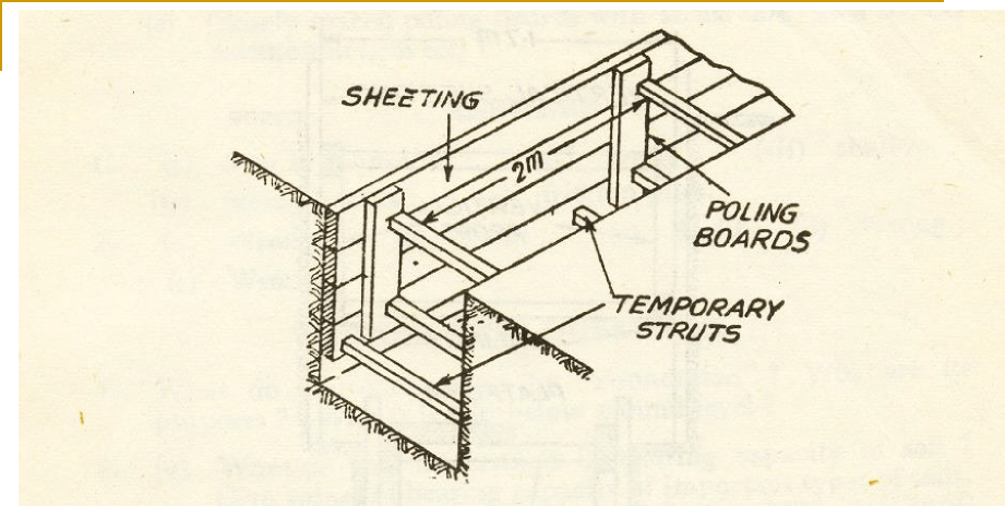
Timbering of trenches in Loose Soil
(With horizontal sheeting)
Timbering of trenches in Loose Soil
(With vertical sheeting)
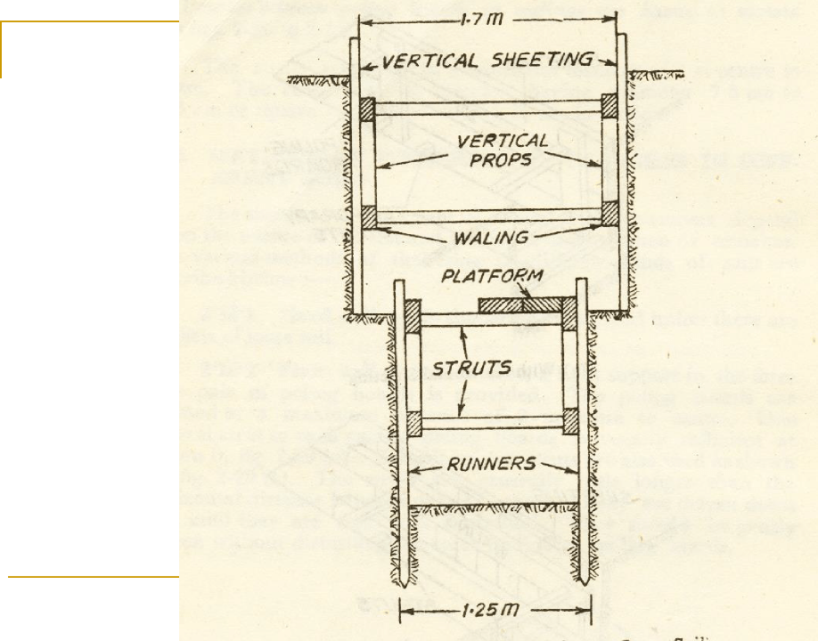
Timbering of trenches in very loose
soil
(With Runners)
Details of Boards (Optional) Slide 20-24
Timbering of Trenches
The various members used in timbering are:-
-
POLING BOARDS
- The members placed vertically on the sides of trenches directly or after providing sheeting are known as Poling boards.
-
The size of poling boards may vary from 1.75 cm x 32 cm. to 22.5 cm. x 4 cm.
- The members placed vertically on the sides of trenches directly or after providing sheeting are known as Poling boards.
(ii) WALING, WALES OR PLANKS
-
The members placed horizontally on sides of the trenches or against Poling boards are known as Walings, wales or planks.
-
The various sizes of Walings are 10 x 7.5, 10 x 10, 15 x 15, 17.5 x 5, 22.5 x 5, 22.5 x 7.5
cm.
- Their length may vary from 2.5 to 4.5 m.
(iii) STRUTS
-
The horizontal members of timber driven across the trenches between Poling boards or Walings are known as Struts.
-
The Struts are driven at a minimum distance of 2 m center to center.
- The Struts may be circular , having diameter 7.5 m to 12.5 cm. or square 7.5 cm. to 10 x 10 cm. in section.
(iii) SHEETING
-
The members which are placed horizontally or vertically close to the sides of the trenches for supporting their sides are called Sheeting.
-
The length of sheeting may vary from 2.5 to 4.5 m.
- The horizontal sheeting is supported by Poling boards and the vertical sheeting by Waling.
(iv) RUNNERS
-
The members which are vertically placed behind the Walings instead of the Poling boards are called Runners.
-
The Runners are long planks about 7.5 cm. thick and 1.75 to 22.5 cm wide.
- They are pointed at their lower end and sometimes provided with an iron shoe and iron cap.
DAMPNESS
The access or penetration of moisture content inside a building through its walls, floors, or roof is known as DAMPNESS.
SOURCES OF
DAMPNESS
-
Damp rising from the soil either through the bottom or through the ground surface, adjacent to the walls.
-
Moisture penetrating the walls as a result of rain beating on them during continued wet weather.
-
Moisture penetrating into the building through defective construction, such as rain water pipes, leaking roofs, leaking or choked gutters, etc.
-
Damp rising from the ground either because there is no damp proof course or because the existing D.P.C. has been bridged by the earth outside, being banked up to form a flower bed or another purpose.
ILL EFFECTS OF DAMPNESS
Read yourself
-
It causes rots to the wooden members provided in the building.
-
It causes corrosion of the metals, used in the construction of a building.
-
It causes peeling off and removal of plaster.
-
It causes paints to get blistered and bleached and the surface thus gets disfigured.
- It causes floors of the building to remain ugly, since they cannot be cleaned well.
ILL EFFECTS OF DAMPNESS
Read yourself
- Carpets if used on the floors of a damped building, gets destroyed earlier.
- All electric installations get destroyed.
- It reduces the life of the structure as a whole.
- When dampness rises into brickwork, certain salts dissolved in it also rise with it and appear in the form of white deposit on the wall surface due to which brickwork disintegrates and falls to powder.
- It causes unhygienic conditions for the occupants of the building and affects adversely their health.
- Dampness produces unpleasant smell, foul air, mildew fungus, which makes it impossible to store supplies of household goods.
CAUSES OF DAMPNESS
Read yourself
-
RAIN PENETRATION
Properly constructed walls offer considerable resistance to rain penetration but its rapid penetration takes place through the joints and porous bricks or stones. Rain penetration is also possible through the roof components, cracks, and joints b/w the walls and the roof.
- LEVEL OF THE SITE
Structures built on a higher ground can be drained off easily and hence they are less liable to dampness. But low lying areas cannot be easily drained off and thus causes dampness in the structure.
CAUSES OF DAMPNESS
-
DRAINABILITY OF THE SITE
Gravel and sandy soil allow water to pass through easily whereas clayey soils retain moisture and also causes dampness due to capillary rise.
-
CLIMATIC CONDITIONS
Dampness is also caused due to the condensation of moisture present in the atmosphere under very cold climate. Condensation of the atmospheric moisture can be identified by the drops of moisture present on the ceilings, walls, floors etc.
CAUSES OF DAMPNESS
-
DEFECTIVE ORIENTATION
Read yourself
The building having its walls subjected to direct showers of rain or getting less direct sun rays, due to defective orientation is liable to dampness.
-
MOISTURE ENTRAPPED DURING CONSTRUCTION
Walls while being constructed are in wet conditions. These may persist moisture for a long period after the construction is over due to the use of salty or alkaline water, which causes dampness in the building.
-
DEFECTIVE MATERIALS
Dampness is also caused due to soakage of moisture by the defective materials like porous bricks, soft stones, etc. especially when they are used in external walls.
-
DEFECTIVE CONSTRUCTION
In case, there is any leakage in the sewers, down water pipes, kitchens, bathrooms, etc., it will be causing dampness in the building.
PREVENTION OF DAMPNESS
PRECAUTIONS
-
Select a site to make sure that the first point at which water is struck in a pit is at least 10ft below the surface of the ground even in the wet season.
-
Make the ground surface surrounding the building slope away from the house so that rain water drains away, before it has time to collect.
- If the building is on a hill side, make sure that the land above the house is adequately drained around the building and not through it
METHODS
The following are the methods that can be adapted for the
prevention of dampness in the buildings:
- BY SURFACE TREATMENT
The surface treatment consists in filling or blinding the pores of the material exposed to moisture by painting a water-repellent material over the surface.
Some of the materials employed are:
Sodium or potassium silicate, aluminum or zinc sulphates, barium hydroxide and magnesium sulphate in alternate applications, soft soap and alum also in alternate applications, lime and linseed oil, coal-tar,
bitumen, waxes and fats, shellacs, resins and gums etc.
(2) BY INTEGRAL TREATMENT
-
The integral treatment consists in adding certain components to the concrete or mortar during the process of mixing, to make it more dense by filling the pores through chemical action or mechanical effect.
-
For example, compounds like chalk, talc, fuller’s earth etc. act mechanically and compounds like alkaline silicates, aluminum or zinc sulphates, calcium, aluminum or ammonium chlorides, iron fillings etc. act chemically.
- If 5% soap is added in the water to be used for preparing the mortar, the pores get clogged and coating of water repellent substance stick to the wall surface which makes it sufficiently damp proof.
(3) BY SPECIAL CONSTRUCTIONAL TECHNIQUES
-
By constructing the external walls of sufficient thickness.
-
By using the bricks of good quality for constructing the external walls.
-
By building the walls in rich cement mortar.
-
By providing string courses and cornices.
-
By fixing down water pipes sufficiently so that water may not leak through the junction of walls and roof.
-
By constructing hollow brick walls.
(4) BY PROVIDING A DAMP PROOF COURSE
The continuous layer of an impervious material, which is provided in between the source of dampness and part of the structure is called a Damp Proof Course.
BY PROVIDING A DAMP PROOF COURSE
Damp proof course is of two types:
-
HORIZONTAL DPC
-
It is provided in the walls at plinth level in the form of 1.5 to 3 in. thick layer of 1:2:4 cement concrete covered with two coat of hot bitumen or a polythene sheet or metal sheets of lead, copper or aluminum.
- It is also provided in the roofs in the form of two coats of hot bitumen, bitumen felt, mastic asphalt or sheets of polythene, lead, copper, or aluminum over the R.C.C. slab.
-
Horizontal D.P.C. is also provided in floors if the sub-soil water table is high and moisture is likely to rise in the floors by seepage, added by the capillary action of the soil.
Fig… J 18:
 .
.
Damp proof course on concrete just
below plinth level.
-
BY PROVIDING A DAMP PROOF COURSE
- VERTICAL DPC
-
Vertical D.P.C. is mostly provided in the external walls in the form of ¾ in. thick 1:3 cement sand plaster, coated with two washings of hot bitumen.
- It is also provided to prevent the dampness into the walls of the basements from the adjacent soils.
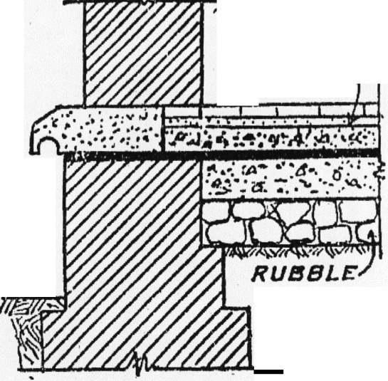
D.P.C. IN BASEMENTS (- ctd -)
-
As basements are built below ground level, these are most likely to be attacked by dampness from the soil below as well as from outside the walls.
-
A typical basement section showing the damp proof courses is shown in fig-119.
-
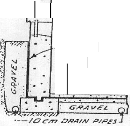
If the head of the water below the level of the floor is high, a layer of gravel 4 ½ in. thick, is laid under the bottom of concrete of floor as shown in fig-120.
- Also, gravel is filed between the walls of the basement and adjacent soil.
D.P.C. IN BASEMENTS
-
The gravel under the floor collects the seepage water and delivers it to the gravel outside the external walls, through the communicating pipes, buried horizontally through the concrete foundation walls.
-
Drain pipes or footing drains are laid around the footing buried
inside the gravel.
-
These footing drains lead the seepage water to a natural drain, if nearby, or to a dry well.
-
A dry well is a pit excavated in permeable soil or one having its bottom in such soil and filled with gravel or crushed rock.
-
If permeable soil is not present nearby, the water is pumped out of dry wells by hand pumps or other techniques.
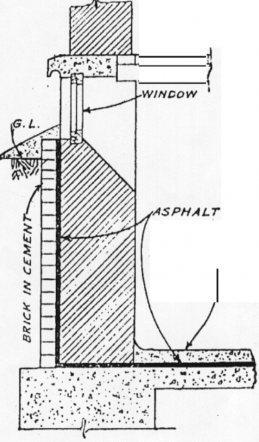
Fig. JJ9 : .
Treatment for waterproofing basement floor.
;jj;
Fig . 120
Constructing a water tight basement by providing a water proof layer at bottom and sides and a drain pipe all round and below the cellar in gravel
DOORS
The arrangements made to provide free and easy access inside and outside the rooms of a building are called Doors.
Whereas, the opening provided in the boundary wall of a building for entrance and exist is known as Gate.
DOORS (-ctd-)
-
Doors are generally made of timber or steel etc. They may also be consisting of plywood, wire gauge, frame work of steel etc.
-
The doors with one shutter are known as single leafed doors. Such doors are used for small openings.
- The doors having double leaves or shutters are called double leafed doors. Such doors are used for large openings.
-
LOCATION OF DOORS
-
Doors should be located in such a way that free movement in and out of the rooms of a building is ensured. Doors should be properly placed in the corner of a room.
- In case the room is to be provided with more than one door, they should be located in the opposite walls to have a good ventilation in that room.
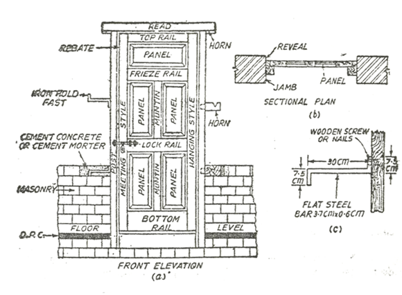
IMPORTANT TECHNICAL TERMS
-
Frame:- An enclosure to provide support for door or window shutter is called frame. It is made from the well-seasoned wood. Head and sill are morticed to take the Tenon formed at the ends of vertical posts. Bamboo pins are used to hold shoulders and the tendons tightly.
-
Head:-The top horizontal member of a door or window frame is called head.
-
Sill:- The bottom horizontal member of a door or window frame is called sill.
-
Posts:- The vertical side members of a door or window frame are called posts.
IMPORTANT TECHNICAL TERMS (-ctd-)
-
Shutters:- The planks, framed, paneled or otherwise which fit in a door or window frame are known as shutters. They are hung to the frame by means of hinges.
-
Styles or stiles:- The vertical side members of frame-work of a shutter are called styles. The style which is hung or hinged to the frame is called a hanging or hinged style. Whereas the style which is not hung or hinged to the frame is called a meeting style.
-
Top rail:- The topmost horizontal member of the frame-work of a shutter is known as top rail.
-
Lock rail:- The middle horizontal member of the frame-work of a shutter where lock sliding bolt is fixed is called lock rail.
IMPORTANT TECHNICAL TERMS (-ctd-)
-
Bottom rail:- The lower most horizontal piece or member of
the frame-work of a shutter is known as bottom rail.
-
Mullion:- The vertical member running through the middle of
frame-work of a shutter is called mullion or mounting.
-
Jambs:- The vertical faces of a door or window opening which support the frame of a door or window are called jambs.
-
Reveal:- The portions of a door or window opening extending beyond the frame towards the face of a wall are called reveals.
-
Sash bars:- The light members of the frame-work which carry the glass panes within a shutter or frame work are known as sash bars.
IMPORTANT TECHNICAL TERMS (-ctd-)
-
Panels:- The small wooden members which are provided between the rails of a shutter or frame- work are called Panels.
-
Rebate:- Depression or cut in the frame of a door or window to receive the shutters is called rebate.
-
Horns:- The projections of head or sill of a door or window frame are known as Horns. These are generally embedded in the masonry to increase their fixing strength.
-
Louver:- The inclined boards fixed in a frame-work are called Louvers.
IMPORTANT TECHNICAL TERMS (-ctd-)
-
Transom:- The horizontal dividing member in a window or door frame provided with fan light is called Transom. It acts a head of the door or window frame and sill of the fan light.
-
Stops:- The timber pieces fixed to the door or window frame on inside to prevent the shutters from damaging the plaster of jambs when fully opened are called stops.
-
Chocks:- The timber pieces hinged to the window or door frame on outside to prevent the shutters from closing under the effect of heavy wind are called chocks.
FIXING OF A DOOR FRAME IN A WALL
-
-
A door frame is fixed in the masonry by hold fasts built into the walls with
cement mortar (1: 5).
-
The hold fasts are made from 3.7 cm x 0.6 cm flat, bent at both ends One end of each hold fast is fixed on the side of the door frame and its other end is built into the masonry.
-
The horns provided at the head and sill or in between, are also built into the walls.
-
Now-a-days, sill is not provided in case of a door frame since it causes obstruction to the free movement and does not permit easy cleaning and washing of floors.
-
Before fixing a door frame, its sides coming in contact with masonry, are painted with two coats of a wooden-preservative (generally coal tar). The other sides of the frame are generally given a priming coat.
TYPES OF DOORS
1- Ledged and Battened 2- Battened and Braced Door
-
Framed, Ledged, Battened 4- Framed and Paneled Door
and Braced Door
5- Paneled and glazed Door.
-
Framed Flush Door (b) Solid Laminated Flush Door.
7- Louvered Door 8- Revolving Door
9- Sliding Door
10- Collapsible Door.
-
Rolling Steel Door 12- Wire-gauged Door
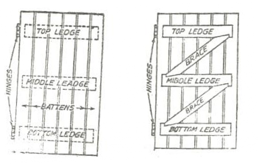
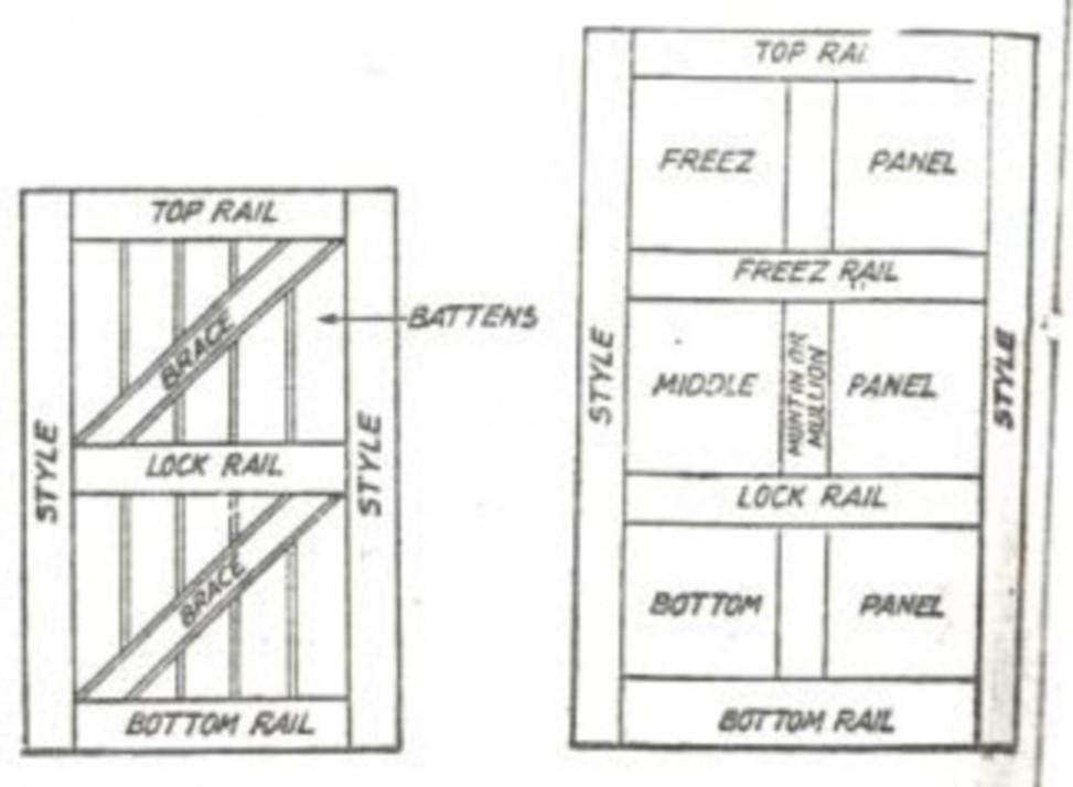
- Ledged and battened doors
- Ledged and battened doors
-
-
-
-
These are the simplest type of doors.
-
They consist of battens (each 15 cm wide and 0.8 to 1.8 cm thick) which are screwed to three horizontal members called ledges.
-
Top ledge is 10 cm x 3.2 cm in cross-section, middle and bottom ledges have section of 17.5 to 20 cm x 3.2 cm.
-
Battens are generally tongued and grooved.
-
These doors are mostly used for narrow openings in temporary houses where appearance is not the main consideration.
- Ledged, battened and braced doors
- Ledged, battened and braced doors
-
This type of door is similar to a ledged and battened door except that they consist of ledges and battens which are strengthened with the help of diagonal members known as braces.
-
The width of braces varies from 10 to 15 cm and thickness is 3.2
cm.
-
The inclination of the braces should be kept towards the side of the shutter to be hinged to the frame as shown in fig. 10-3.
-
These doors can be used for comparatively large openings in ordinary houses and in places where appearance is not so important.
-
Framed, ledged, battened and braced doors
-
-
This is a better and strong type of door.
-
They consist of two stiles, three rails and two braces forming the frame-work of each leaf (shutter) to which he battens are fixed.
-
The frame-work is made with mortice and Tenon joints.
-
The top and bottom rails and the stiles have full thickness while the middle (lock) rail and braces are thinner in section to allow the battens to pass over them and finish flush with the top and bottom rails.
-
The battens should butt into the rebate in the top and bottom rails.
-
These shutters are hung to the frame by means of butt hinges.
-
These doors are mostly used as external doors in ordinary residential buildings, shops etc.
- Framed and paneled doors
- Framed and paneled doors
-
This is the most common type of door.
-
They are made in different designs but their principle for construction is same as in other doors.
-
They consist of frame-work of styles, rails and mentions or mullions of same
thickness.
-
The space between them is filed with panels. The vertical styles are continuous from top to bottom and rails are jointed to the styles.
-
On inside of the styles and rails, grooves are made to receive the panels which may be of raised or flush type.
-
These shutters are hung to the frame by means of butt hinges.
-
These doors are mostly used in residential and other buildings as internal and external doors.
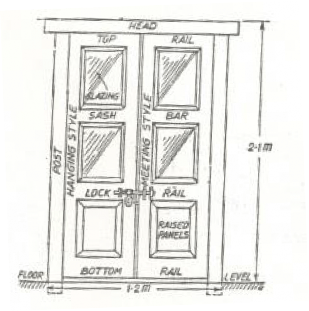
- Paneled and glazed doors
- Paneled and glazed doors
-
The construction of this type of door is similar to a framed and paneled door
but in such doors glass panes are fixed.
-
In these doors, instead of wooden panels in their top portions, sash bars to receive the glass panes are used.
-
Sash bars are equal in thickness to the full thickness of the shutter, with 2.5 cm with and having 1 to 3 cm rebate according to the size of the doors.
-
The size of the rebate is generally 1.6 cm x 0.6 cm. Each glass pane is secured
in position by small nails and is bedded with the help of lime-putty.
-
It may be either 1/3rd glazed at top and2/3 paneled at bottom, or 2/3 glazed at top or 1/3 paneled at bottom.
-
These doors are mostly used in public buildings, hospitals, colleges, offices and also in residential buildings.
-
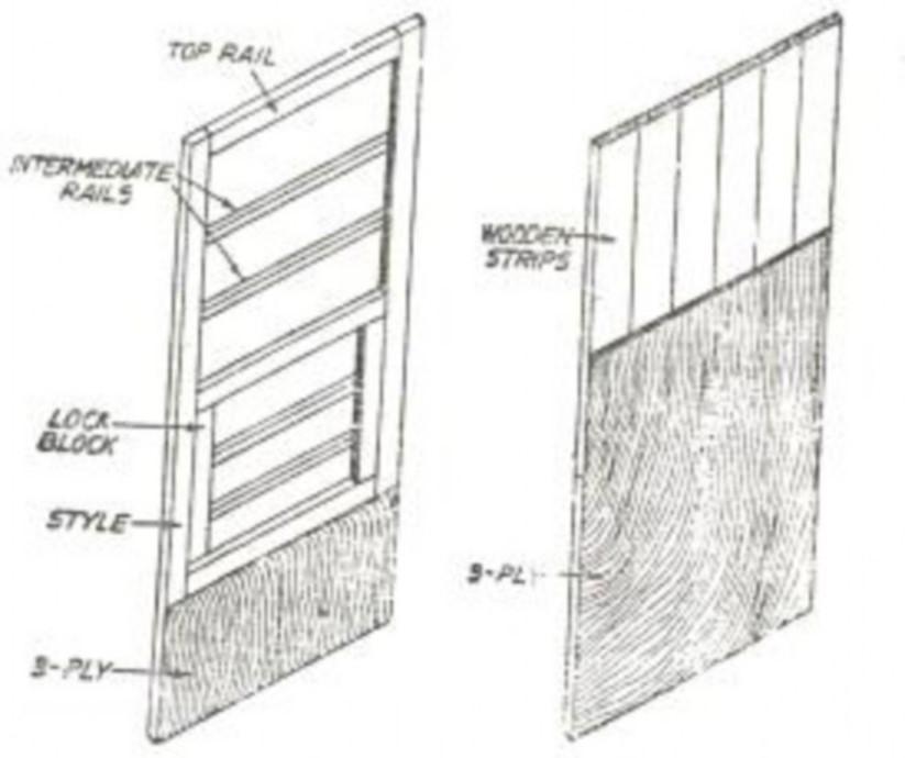
Flush doors
-
-
These doors are made with plywood and give better appearance.
-
They are solid and semi-solid door and are constructed and finished in many ways.
-
The inner core is either framed or laminated. The later makes a more solid and lasting door.
-
These doors do not catch dust and are easy to clean.
-
With the production of plywood in large quantities, flush doors are becoming more and more popular these days.
-
These doors are mainly used as internal doors in residential buildings,
restaurants, public and other important buildings.
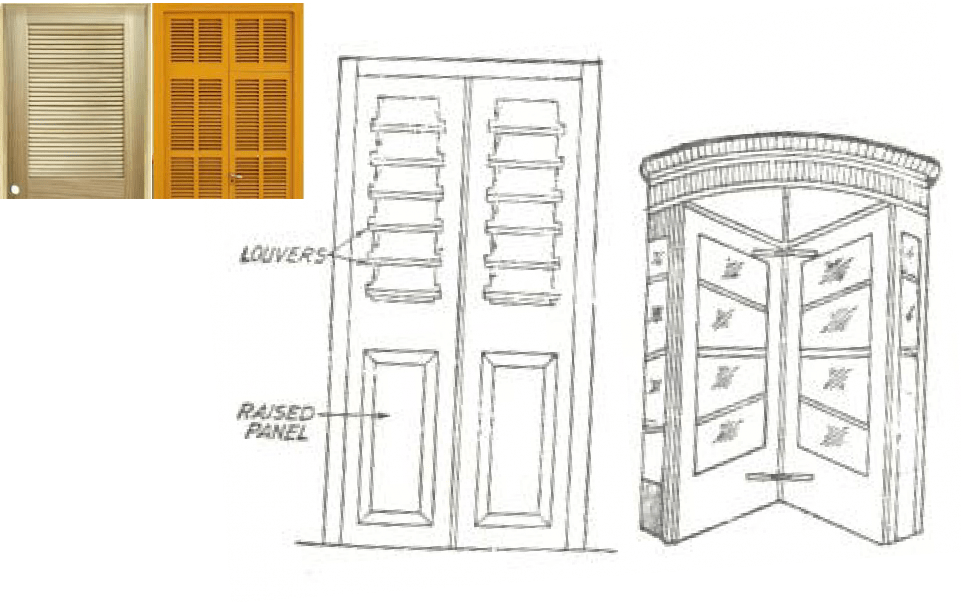
- Louvered doors
- Louvered doors
-
These doors are similar to glazed and paneled doors. But in these doors, the spaces between the rails and stiles are filled with series of wooden members called louvers.
-
The louvers are fixed into the stiles or made movable.
-
In order that they may be effective and economical, are fixed at an angle of 45 degree.
-
These doors allow free passage of light air and secure privacy and safety. But they collect dust easily and are difficult to clean.
-
These doors are mostly used in school, workshops or at place where sufficient privacy is required besides admitting air and light freely.
- Revolving doors
- Revolving doors
-
These doors consist of four shutters, arranged diagonally, revolving on a common vertical axis.
-
Paneled, glazed or both types of shutters may be used for these doors. They allow entrance on one side and exit on the other side.
-
These doors are used where there is constant foot traffic of people coming in and going out of an entrance in public buildings such as offices, banks, restaurants, hotels, theatres, and other public buildings.
-
They are also used in hill stations to prevent strong wind blowing inside the building directly.
-
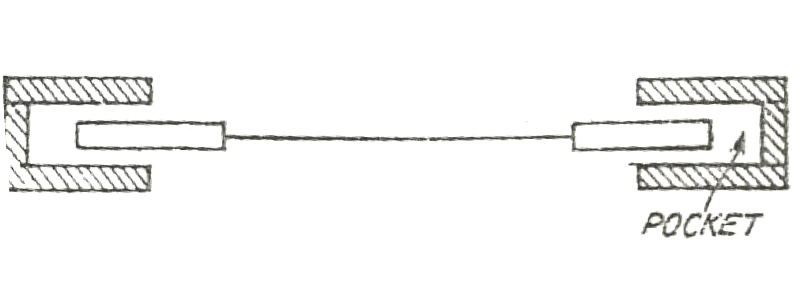
Sliding Doors
-
These doors consist of single or double steel or wooden shutters.
-
They slide into the pockets provided in the masonry wall.
- These doors are commonly used for workshops, garages and on windows in shops etc.
-
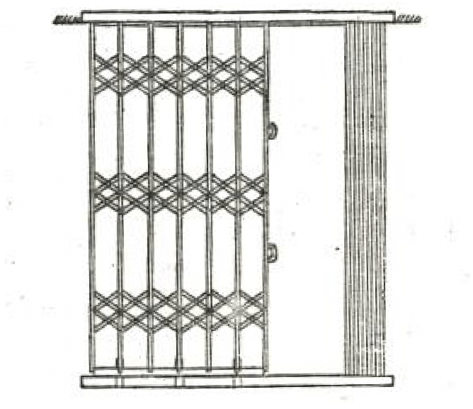
- Collapsible Doors
-
-
These doors consist of frame work of rolled steel sections and
are provided with rollers at bottom which roll on rails.
-
These doors are rolled when they are to be opened or collapsed.
-
Flat iron pieces are used cross wise and are fixed to vertical flat iron pieces at 12 to 15 cm center to center so as to form parallelograms. When pushed, the parallelograms get collapsed.
-
These doors are used in public buildings such as banks, railway
stations, sheds, workshops etc.
- Rolling Steel Doors
- Rolling Steel Doors
-
These doors are generally made of thin corrugated steel plates ( or sheets) which roll up on a roller or drum.
-
The shutter slides in grooves in the side walls.
-
The shutter may be counter balanced by sprigs so that it can be easily raised on lowered by hand.
-
These doors are sufficiently strong and may be safely used in exposed places.
-
These doors are mostly used for main entrance of shops, showrooms, and garages
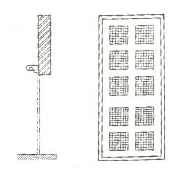
- Wire-gauged doors
- Wire-gauged doors
-
These doors are normally hung on the same chowkhat (frame)
as other door and window shutters of the frame.
-
The thickness of the frame is increased suitably to cut the rebate for the wire gauged shutters.
-
These doors allow free passage of the air and light and at the same time do not allow entrance of flies and mosquitoes inside the rooms of a building.
- These doors are mostly used in kitchens and dining rooms of
residential buildings


