
T & L Beams
Lecture 13
Design Principles
of Concrete Structures
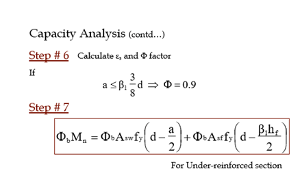
Capacity Analysis
Known: b, d, bw, hf, L, fc’, fy, As
Required: ΦbMn
Step # 1: Check whether the slab is in tension or not, if Yes,
analyses as a rectangular section.
Step # 2: Assume the N.A. to be with in the flange and calculate
the “a” and “c”

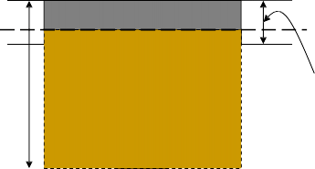
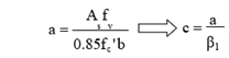
If c ≤ hf Our assumption is correct
and beam will be designed as
rectangular beam. (b x h)
Example No. 1
Example:
A T-Beam has the following data:
| b = 800 mm | bw = 350 mm |
hf = 125mm |
| fc’ = 20 MPa | fy = 420 MPa |
d = 450 mm |
Determine the flexural strength for the following two cases if the slab is in compression.
- As = 3900 mm2
- As = 3000 mm2
Design of T & L Beam
Known: Required:
hf, L, fc’, fy, Loads or Mu
beam size, As, detailing, bar bending schedule

Step # 1: Select trial dimension of the beam, bw & h, nearly same as for
the rectangular section.
Step # 2: Calculate the effective width “b”.

Step # 3: Assume the N.A. to be at the junction of flange and web, means
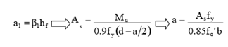
If a1 ≤ β1hf Our assumption is correct and beam will be designed as rectangular beam. (b x h)
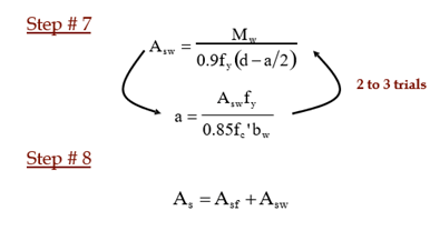
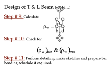
Design of T & L Beam (contd…)
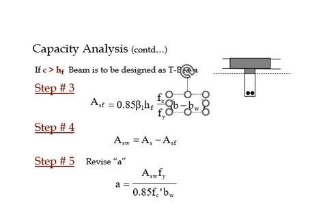
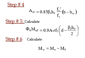
If a1 > β1hf and beam will be designed as T-beam.
Design of T & L Beam (contd…)
Example No. 2
Example:
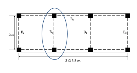
Design a T-Beam to be used as interior simply supported beam of span 5m. The slab panels on both sides of the beam are 3.5m x 5m. Factored slab load is 15 kN/m2. fc’ 17.25 MPa and fy = 420 MPa.
bw = 300 mm hf = 125 mm Use SI bars
- Design for given loading
- Design for Mu= 1000 kN-m
Concluded


