

Design Principles of Concrete Structures
Lecture 4
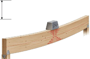
Study of Flexural Behavior
(Derivation)
Assumption for the Study of Flexural Behavior
-
Plane sections of the beam remains plane after bending.
-
The material of the beam is homogeneous and obeys hooks law
Stress ∞ Strain
-
Perfect bond exists between steel & concrete so whatever strain
is produced in concrete same is produced in steel.
- All the applied loads up to to failure are in equilibrium with the internal forces developed in the material.
- At the strain of 0.003 concrete is crushed.
Assumption for the Study of Flexural Behavior
- When cracks appear on the tension face of beam its capacity to resist tension is considered zero.
-
Stress and strain diagrams for steel and concrete are simplified.
Flexural Behavior Beams

General Procedure for the Derivation of Formula

Step # 1 Draw the cross section of beam with reinforcement. Step # 2 Draw the strain diagram for the cross section.
C
la
Step # 3 Draw the stress diagram.
Step # 4 Show location of internal resultant forces.
Step #5 Write down the equation for given configuration
Flexural Behavior Beams (contd…)
-
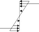
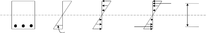
When Both Steel and Concrete are in Elastic Range
C
la
εs
f
T
s
εc fc
N.A.
Strain Diagram
Stress Diagram Resultant Force
Diagram
Both steel and concrete are resisting to applied action
Flexural Behavior Beams (contd…)
-
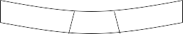
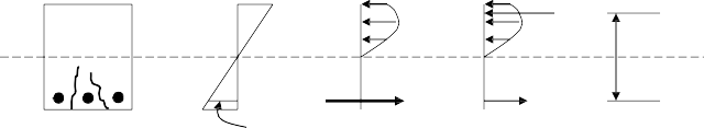
When Cracks are Appeared on tension Side

C
εs
fs
T
la
εc
-
Strain Diagram
fc
Stress Diagram
Resultant Force Diagram
N.A.
When the tension side is cracked the concrete becomes ineffective but the strains goes on increasing. The steel comes in to action to take the tension.
Flexural Behavior Beams (contd…)
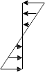
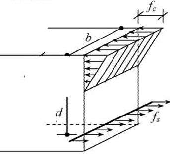
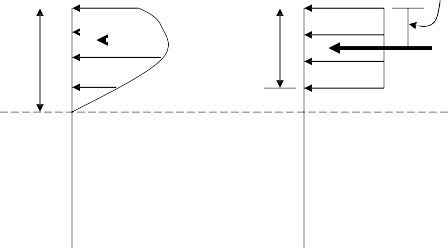
- When Compression Stresses Cross Elastic Range
Stress
fc’
0.85fc’
εc 0.85fc
fs
Strain
C
la N.A.
T
s
ε
Strain Diagram
Stress Diagram
Resultant Force Diagram
It is clear that the stress diagram is obtained by rotating the stress strain diagram
of concrete.
Strains keeps on changing linearly in all three cases.
Flexural Behavior Beams (contd…)
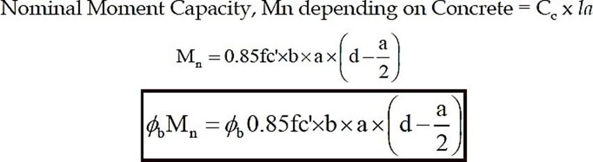
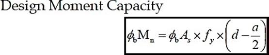
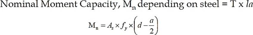
Final Equation for Calculating Moment Capacity
M(moment capacity) = T x la = C x la
Ultimate Strength Design of Beams
(Strength Design of Beams)
Strength design method is based on the philosophy of dividing
F.O.S. in such a way that Bigger part is applied on loads and
smaller part is applied on material strength.
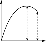
favg = Area under curve/0.003
If fc’ ≤ 30 MPa
favg = 0.72 fc’
β1 = Average Strength/Crushing Strength
β1 = 0.72fc’ / 0.85 fc’ = 0.85
fc’
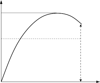

Stress
favg
0.003
Crushing Strength
0.85fc‘

Strain
b
εcu= 0.003
0.85fc‘
0.85f ‘
c
a
c
a/2
Cc
h
d
N.A.
la = d – a/2
εs
Strain Diagram
f
s
f
s
Actual Stress Diagram
Equivalent Stress Diagram/ Whitney’s Stress Diagram
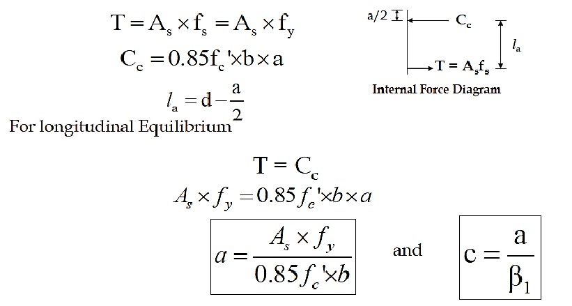
T = Asfs
Internal Force Diagram
Ultimate Strength Design of Beams (contd…)
In ultimate strength design method the section is always taken as cracked.
c = Depth of N.A from the extreme compression face at ultimate stage a = Depth of equivalent rectangular stress diagram.
Ultimate Strength Design of Beams (contd…)
-
The resultant of concrete compressive force Cc,
0.85fc‘ 0.85fc‘
a/2
acts at the centriod of parabolic stress diagram.
- Equivalent stress diagram is made in such a way c
that it has the same area as that of actual stress diagram. Thus the Cc, will remain unchanged.
Cc a C
Actual Stress Diagram
Equivalent Stress Diagram/ Whitney’s Stress Diagram
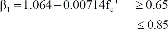
Factor β1
β1 = 0.85 for fc’ ≤ 28 MPa
Value of β1 decreases by 0.05 for every 7 MPa increase in strength with a minimum of 0.65
Determination of N.A. Location at Ultimate Condition
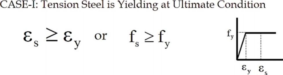
CASE-I: Tension Steel is Yielding at Ultimate Condition
This is general
procedure for calculations of N.A Depth & Moment Capacity
CASE-I: Tension Steel is Yielding at Ultimate Condition (contd…)
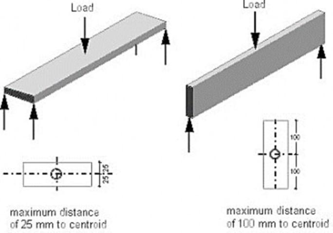
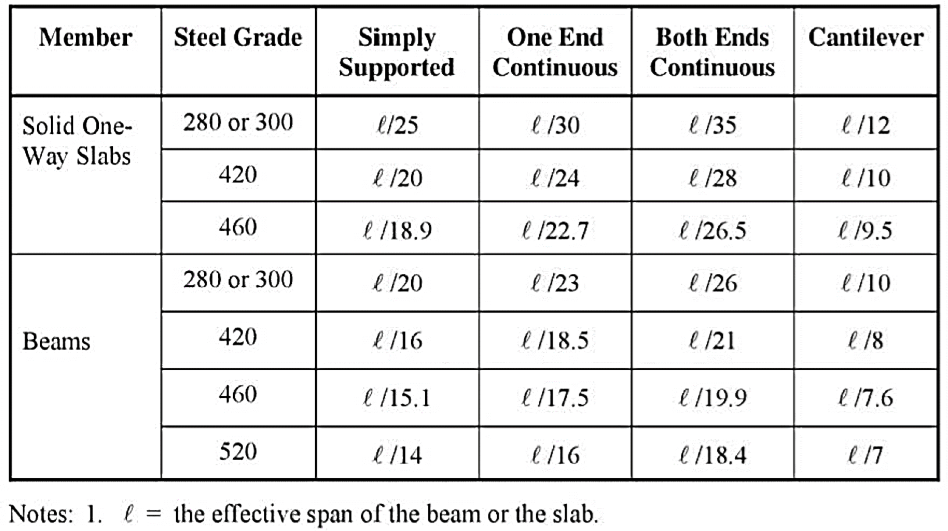
Minimum Depth for Deflection Control
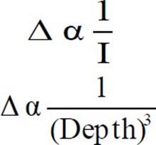
Deflection Depends upon Span, end conditions, Loads and fy of steel.
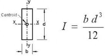
Example – Moment of Inertia

Minimum Depth for Deflection Control ACI 318 (Contd…)


Concluded


