Structural frame elements
Columns
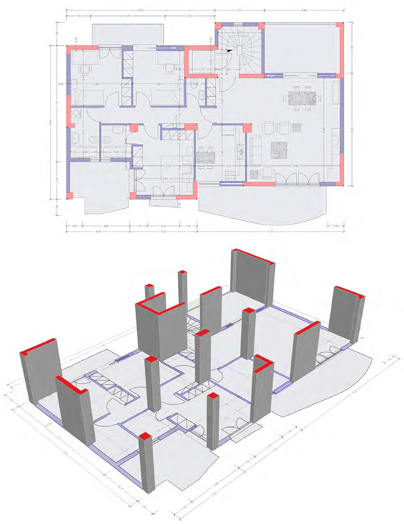
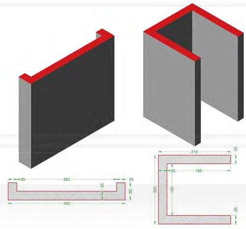
The vertical load bearing elements of the structural frame are usually called with their common name, columns. However due to their varied behavior, their different design rules and most of all, their differences in reinforcement and detailing, they are separated into three major catego- ries: columns, shear walls and composite elements.
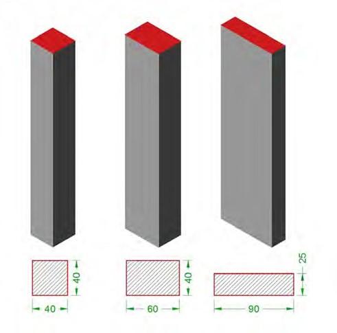
Columns are the rectangular elements in which the larger dimension is lesser than 4 times the smaller dimension e.g.40/40, 40/60, 25/90, etc.

The columns category may also include elements with “Γ”, “T” or “Z” cross-sections, in which the dimension ratio of their orthogonal parts is lesser than 4 e.g. “Γ” cross- section 40/80/25/25, “T” cross-section 70/50/25/25, “Z”cross-section 60/70/90/25, etc.
The columns category includes circular sections as well, for example D=50 and quadrilateral sections like 50/60 with an inside angle equal to 60˚.
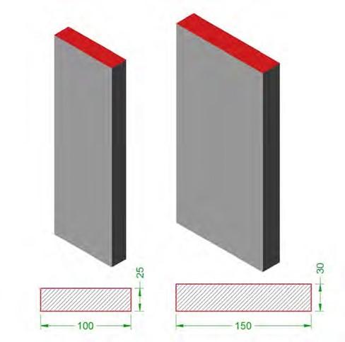
Shear walls are rectangular elements with a length to thick- ness ratio greater or equal to 4
e.g. cross-sections 100/25, 150/30.
Composite elements are com- prised by one or more rectangu- lar elements, at least one of which must be a shear wall. Broadly speaking and due to the fact that at the two ends of each shear wall, columns are formed, a wall can be character- ized as a composite element. For example a wall with ” Γ” cross-section 120/100/25/25, “Γ” cross-section 120/70/25/25, elevator cores with or without flanges, double elevator core with gradient on side etc are composite elements.

Beams
Beams are the vertical or sloping bearing elements of the structural system that connect col- umns and support slabs.

Various types of beams
<project: beams>
When beams support slabs, they work together thus forming a “T” section beam. The level of the slabs compared to the level of the beams results in the formation of rectangular beams, inverted beams or “Z” beams.
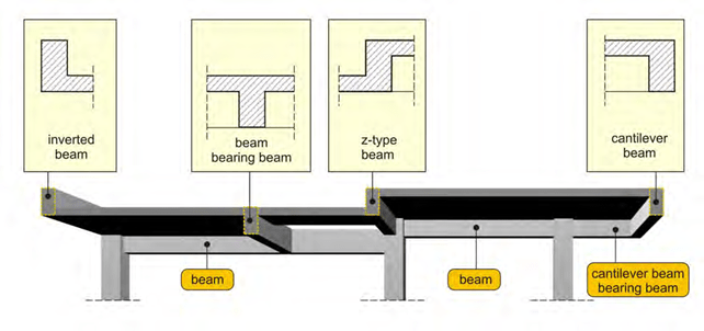
Generally, beams are supported by columns (beam to column connection). However, some- times one or both beam ends are supported by another beam (beam to beam connection) and other times only one end is supported by a column or beam while the other end has no support at all. The beam supported only in one end is called cantilever.
The beam to column connection is called direct support and the beam to beam connection is called indirect support.
The most commonly used beam is the one supported by two columns and the most scarcely used is the cantilever beam. Indirect supports should be rarely used and only when there really is no alternative solution.
In tilted roofs, both beams and slabs have cross sections and supports like the ones mentioned above but they are sloped.
Slabs
Slabs are surface plane elements that bear loads transverse to their plain.
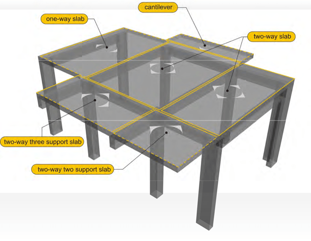
Structure with various types of slabs met in construction
<project: slabs>
Most of the times, slabs are statically indeterminate elements that consequently redistribute the stresses applied to them. This ability makes them highly secure against bending and shear failure. Cantilevers are excluded since slabs which are statically determinate elements and therefore need special care in their construction.
Slabs are separated into categories dependent on their supports:

Hypothetical formwork plan, where the arrows show the supported sides of slabs
One-way slabs (Simply supported)
They are those supported on two out of four, opposite sides like Π1 of the above example.
Two-way slabs
They are those supported on all four sides like Π2, Π3 of the above example
Cantilever slabs
They are those with a fixed support on only one out of four sides, like Π4 of the above example.
Two-way three support slabs
They are those supported on three out of four sides, like Π5 of the above example.
Two-way two support slabs
They are those supported on two adjacent sides, like Π6 of the above example.
The above categorization regards rectangular slabs and is applicable only when the side sup- ports are clearly defined in their full length. When a slab has a general polygonal shape it can be approximately simulated as a similar orthogonal shaped slab.
The slab’s essential thickness is determined according to the required flexural and shear strength capacity as well as to the limitations of the allowable deflections. Usually the determi- native factor is the second parameter because the slab’s elastic stability (stiffness) is important throughout the entire service life of the structure. Its lack can even become apparent with hu- man walking as it may initiate vibrational motion.
As regards to support, the safest slab is the two-way slab and the most vulnerable is the canti- lever slab. This happens because in a two-way slab, potential loss of one support results in a two-way three support slab, while in the case of a cantilever slab potential support loss results in collapse.
Slabs behave better when having one adjacent slab and even better when having two adjacent slabs in both directions.
The following picture shows deformations, in a large scale but proportionate to one another, for three different types of slab continuity. It is obvious that continuous slabs suffer lighter deflec- tions thus they have better elastic stability (stiffness).
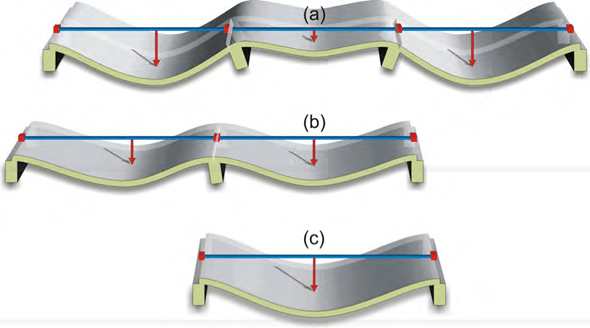
The slab with the bilateral continuity (a) behaves in the best way. Next comes the slab with the unilateral continuity
(b) while last comes the slab with no continuity (c).
In common structures, for slab thickness equal to 15cm, the slab’s span may vary between 3.60m and 6.00m and the cantilever spans may be up to 1.50m. For slab thickness equal to 20cm the slab’s span may range from 4.80m to 8.0m and the cantilever spans may be up to 2.0m.
The 15cm thick slab has a self weight equal to 0.15m*25 kN/m³=3.75 kN/m² while the live load due to human use, furniture etc that it is called to bear, is equal to 2.0 kN/m² only. If the slab has a thickness equal to 20cm its self weight is 5.0 kN/m², and if it is equal to 30cm its self weight is
-
kN/m² whereas the live loads remain the same.
Therefore for large spans ribbed slabs (waffle slabs) (Zoellner, sandwich) can be used, like the one shown in the figure below. A ribbed slab with total thickness of 30cm may have a self weight equal to 3.75kN/m², which corresponds to the self weight of a 15cm thick solid slab.
Advantages of ribbed slabs:
- their large effective thickness provides them with a high level of elastic stability (stiffness),
- they have low dead weight consequently they apply relatively light stresses,
- they do not overload the structural frame and the foundation,
- because of their large effective thickness they comparably need lesser amount of rein- forcement,
Disadvantage of ribbed slabs:
- Their construction is more challenging and therefore they require meticulous reinforce- ment detailing.
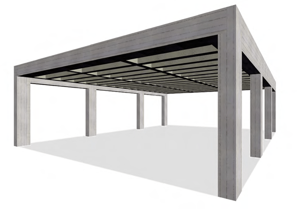
One–way ribbed slab
<project: zoellner10>
A one-way (simply supported) ribbed slab, in the primary direction is composed by usual ribs while in the secondary direction the ribs are vertical and sparsely placed thus ensuring the even load distribution.
The voids between the ribs are usually covered with extra light-weight polystyrene with a density of e.g. 25kg/m³ (compared to the density of the reinforced concrete that is equal to 2500kg/m³)
Usually two-way slabs have square voids between the ribs because the demand for adequate bending strength is equal in both directions. The square voids are being shaped either with the use of light-weight fillings like polystyrene or with the use of plastic moulds. The later have sig- nificant constructive advantages (qualitative, fast construction) thus providing proportional eco- nomical solutions.

Two–way ribbed slab
<project: zoellner20>
Staircases
Although stairs are not part of the structural load bearing frame, they affect and they are af- fected by its behavior especially when horizontal loading is applied, mainly due to seismic ac- tions.
If the staircases are both properly placed in the structure’s plan and properly constructed they may even enhance the structure’s antiseismic behavior

Staircases are architectural-service elements, they are cast together with the load bearing frame which they affect and they get affected by.
The main concern is to ensure that in the duration of a seismic event, stairs will not suffer seri- ous damage. As a result, after a strong earthquake, their repair will be technically and economi- cally possible but most important of all they will remain in service allowing the evacuation of the structure since the elevator use will be prohibited.
Foundation
The same way humans have their feet to transfer their self weight and other loads, softly to the ground, foundations carry with light pressures the structural frame loads to the underlying soil.
Foundation generally includes the footings and the pedestals. The simplest type of foundation is the spread foundation (pad foundation) i.e. isolated column footings.

Foundation consisting of flexible and rigid spread footings (no connecting beams)
<project: Foundation10>
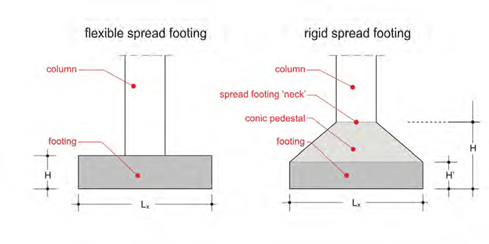
As a rule, spread footings consist only of a box and they are usually called flexible. Sometimes they may have a relatively large height and a sloped end, and they are called rigid.
Nowadays, flexible spread footings are used almost exclusively because of their easy construc- tion and their low cost and labor. However in the past, when the material cost was higher than the labor cost, rigid spread footings were usually constructed.
The footings’ dimensions depend on the soil’s quality and the loads transferred by the columns (column loads are determined by the distance between the columns along with the number and loads of the structure’s storeys). The usual footing dimensions range from 1.0×1.0m to 3.0×3.0m although sometimes they may be larger and their height varies between 0.50m and 1.00m for flexible spread footings and between 0.70 and 2 m for rigid spread footings.
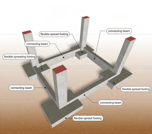
Foundation consisting of flexible spread footings and connecting beams
<project: Foundation20>

In order to ensure the proper behavior of the foundation, the use of foundation beams (connect- ing beams) is mandatory. These beams tie together the column’s bases thus making the foot- ings behave in a normal way especially during seismic incidents. Usually their cross section width ranges from 0.30 και 0.50m and their cross section height from 0.50 έως 1.50m.
Footings are constructed centrically to their mass centre, except in those cases when due to building restrictions they are eccentrically constructed e.g. like boundaries of the building line or edge of the building land as shown below.
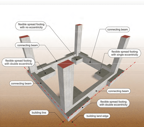
Foundation consisting of eccentrically constructed spread footings due to limitations of the building line and the edges of the building land
<project: Foundation30>
The bigger the footing’s construction eccentricity is, the strongest must the connecting beam in that direction be.
Spread foundation (pad foundation) is used in a good quality soil. In case of low soil capacity strip foundation is used.

Strip foundation with connecting beams
<project: Foundation040>

Strip foundation consists of the pedestal and the footing. The usual dimensions of the footing vary between 0.40m to 0.60m for its thickness and between 1.00m to 2.50m for its width. The typical pedestal cross sections range from 0.30×0.80 to 0.50×1.50.
For a more effective behavior it is advisable to use grid foundation.
In poor soil conditions raft foundation is commonly constructed. It consists of a slab which ex- tends over the entire loaded area. Frequently it is used in other soil conditions for practical rea- sons basically because of its fast and easy construction.

Raft Foundation with connecting beams
<project: Foundation50>
Raft foundation may have regular foundation beams for rib formation, as shown in the above figure, or beams incorporated into the foundation with the form of hidden beams.
The usual thickness of a raft foundation, ranges from 0.40m to 1.0m, while the dimension of the raft foundation beams vary from 0.30×0.80 to 0.50×2.00.

Two level foundation
<project: Foundation60>
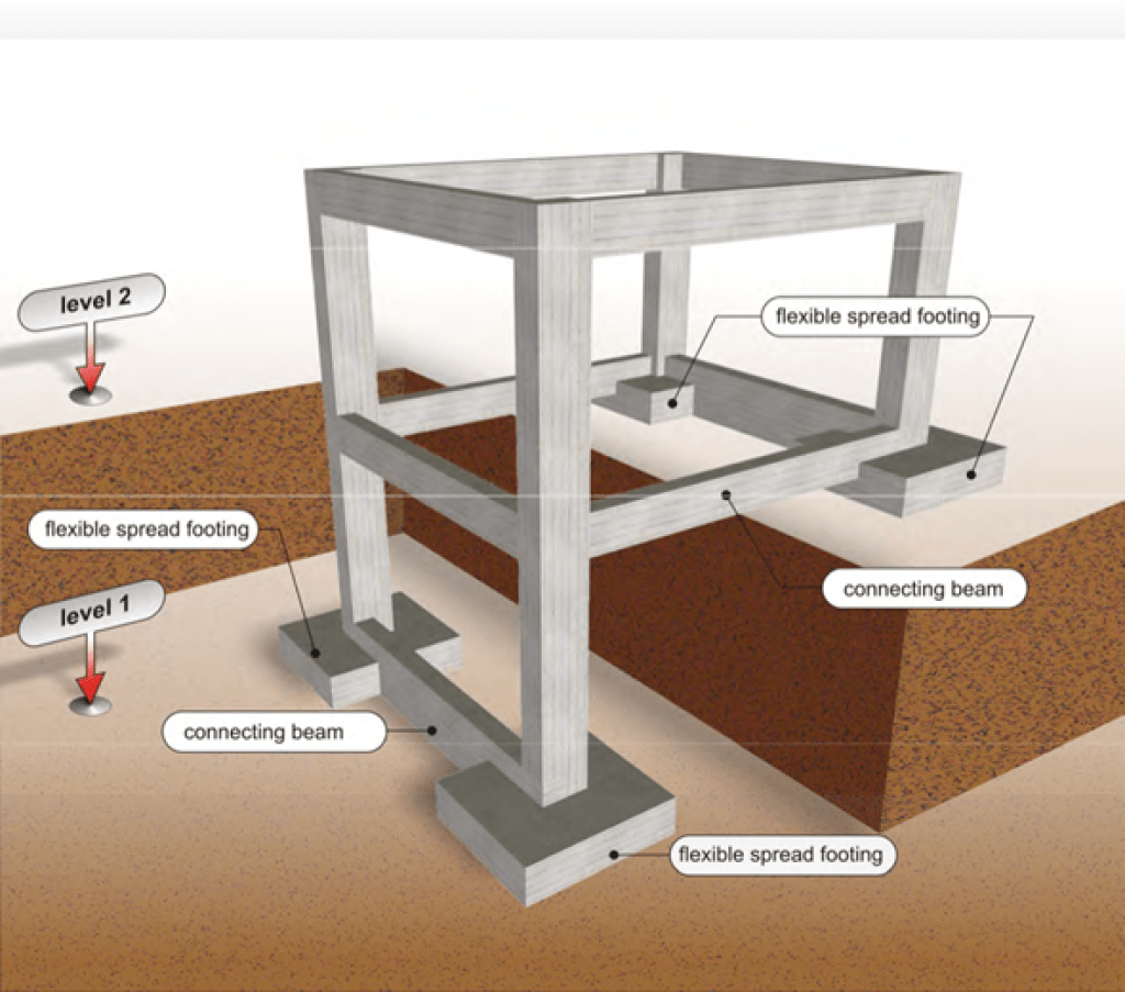
Generally foundation should be placed in one even level however in certain cases like sloped building lands, foundation is placed on more than one levels.

