CALLOUTS & WALL SECTIONS
Sheet A-10 – WALL SECTIONS
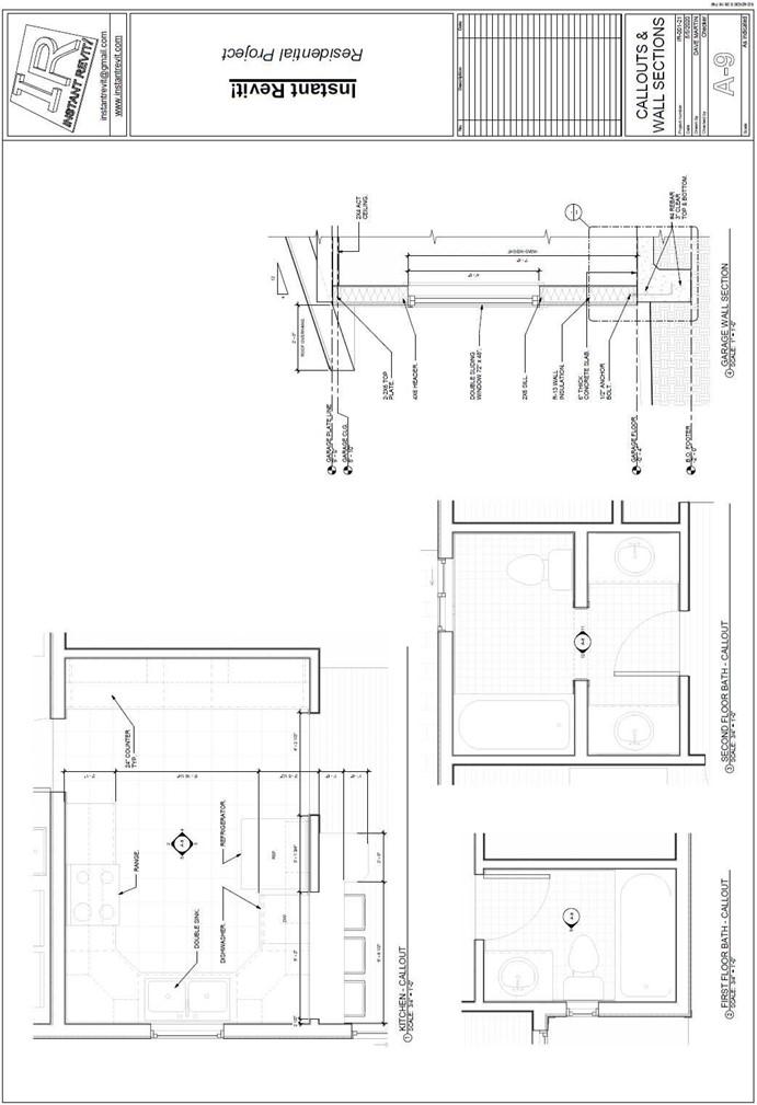
Callouts & Wall Sections
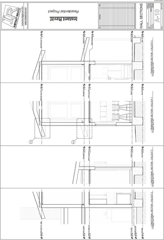
Wall Sections
Creating the Sheet View
- Open the RL7-8 file. Save the file as RL7-9.
- Make the following changes to the Garage Wall Section view.
- In the Manage, Settings, Project Units tool, change the Rounding setting to the nearest 1/2″.
- Use the Join tool to join the rafter and ceiling joist together.
- Draw a wide line over the ceiling joist end and add a hidden line to show the rafter is behind the ceiling joist.
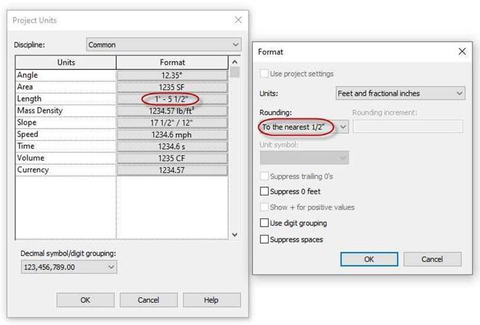
Project Units Settings Changed
- Create a sheet for the callouts and wall sections. This will be the A-9 sheet.
Create a second sheet for the additional wall sections. This will be the A-10 sheet.
-
On sheet A-9, the scale of the three callouts is 3/4″ = 1′-0″. Change the garage wall section to 1′ = 1′-0″.
List of views to be added to Sheet A-9:
- 1. Kitchen – Callout
- 2. First Floor Bath – Callout
- 3. Second Floor Bath – Callout
- 4. Garage Wall Section
- On sheet A-10, the scale for the four wall sections is 3/4″ = 1′-0″.
List of views to be added to Sheet A-10:
- 1. Longitudinal Section – Callout 2
- 2. Longitudinal Section – Callout 3
- 3. Transverse Section – Callout 1
- 4. Transverse Section – Callout 2
- Change the name of the PLATE LINE level at the second floor to SECOND FLR. PLT. LINE.
- Drag and drop each of the views onto the sheets.
- Use the Title w Line – Medium Text type for the view labels on both sheets.
- After placing the views line up the views with one another.
- This is the end of Part 9. Save your file as RL7-9.
![AutoCAD shortcuts & hotkey guide [All]](https://civilmdc.com/learn/wp-content/uploads/2020/06/AutoCAD-Shortcut-keys-scaled-e1591837739256-931x1024.jpg)