Adding the Ceilings and Creating the Reflected Ceiling Plans
In this part you will add the Ceilings and then create the Reflected Ceiling Plans (RCP) for the First Floor, Garage, and Second Floor.
Adding the First Floor Ceiling
- Open the RL5-1 file. Save the file as RL5-2.
- In the Project Browser, go to the Ceiling Plans category and click on the First Floor view.
This is the First Floor Ceiling Plan view.
Turn off the interior and exterior elevation marks.
View Range Settings for First Floor RCP
- In the Properties Box, go to the View Range section and click on the Edit… button.
Note that the cut plane is set to a point just above the door and window openings.
Note: RCP = Reflected Ceiling Plan
First Floor RCP
- Close the View Range dialog box.
- Click on the Ceiling tool in the Architecture tab, Build panel.
Ceiling Tool
- In the Properties Box, select the Compound Ceiling: GWB on Furring. Click the Edit Type button to open the Type Properties for the ceiling type.
- Duplicate the type and rename it GCB on Wood Furring.
New Ceiling Type
- Click the Edit… button next to Structure.
-
Click on the Gypsum Wall Board material and duplicate it. Name the new material Gypsum Ceiling Board.
Set the foreground pattern to Gypsum-Plaster.
- Change the thickness of the material to 5/8″.
-
Move the layer into the core boundary and remove the Metal Stud layer.
- Change the thickness for layer 2 to 5/8″.
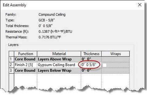
GWB on Wood Furring Layers
- Click OK to apply the changes and to close the Edit Assembly dialog box. Click OK again to close the Type Properties dialog box.
- Exit the Ceiling tool. Select the interior walls on the first floor.
You may select all the interior elements and use the Filter tool to filter out the walls category to quickly select the 10 walls.
- Walls are selected.
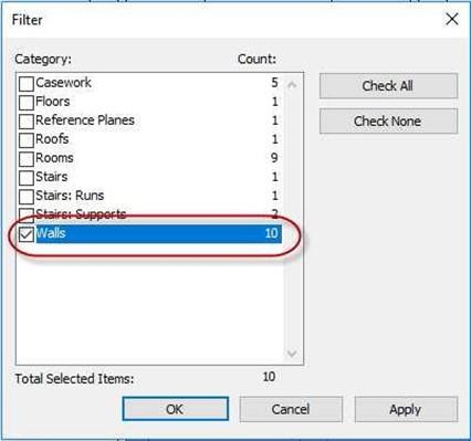
Walls Filtered Out
Walls Selected
-
Set the top offset of the walls
to 8′-1″.
This is done so that the tops of the walls are 1″ above the height of the ceiling. This way the ceiling will stop at the edge of the walls.
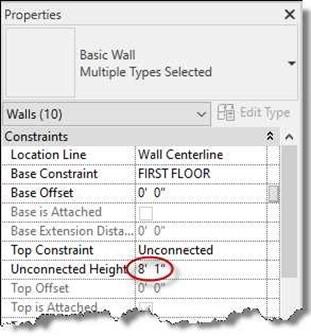
Tops of Interior Walls Set to 8′-1″
- Click on the Ceiling tool.
Confirm that the Ceiling is set to a
height of 8′-0″.
- While still in the ceiling tool; click inside the Living Room, Bedroom, Bathroom, Closet, and Hall.
You will create a total of five ceilings.
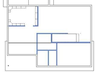
Ceilings Created
Ceiling Height Set to 8′-0″
- If the Automatic Ceiling does not create a boundary, you will need to use the Sketch Ceiling tool.
After clicking the tool, use the draw tools to create an enclosed boundary around the inside edge of the walls.
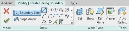
Sketch Ceiling Contextual Tab
Creating the Second Floor Opening
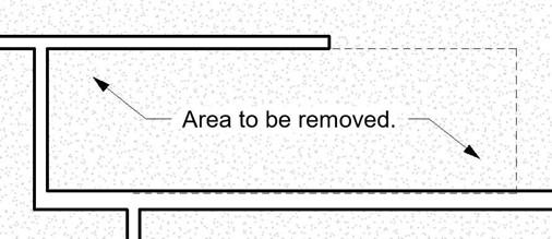 You will need to modify the ceiling in the Living Room. The ceiling is blocking access to the Second Floor.
Area to be Removed
- Select the edge of the Living Room Ceiling and click the Edit Boundary tool.
You might need to draw a crossing fence at the edge of the room and use the Filter option to filter out the ceiling.
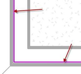
- Use the Pick Lines option in the Draw panel to pick the new boundary.
Pick on the edge of the second floor, not the edge of the stairwell.
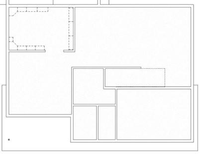
- Your new boundary should look like this…
Note: Edges shown in black for clarity.
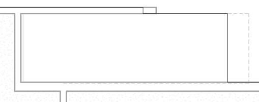
New Ceiling Boundary at the Opening
- Click the Green Check to apply the changes. The ceiling is modified.
Creating the Garage Ceiling
- Zoom in on the Garage Area.
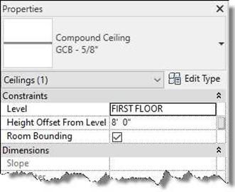
- Click on the Ceiling Tool and select the Compound Ceiling 2′ x 4′ ACT System.
Set the Level to Garage Floor and the
Height Offset From Level to 8′-4″.
Note: ACT = Acoustic Ceiling Tile.
.
- Click inside the Garage.
If the boundary of the garage does not highlight, use the Sketch Ceiling tool.
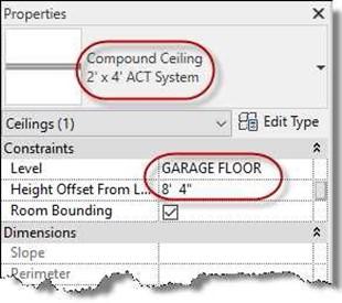
Compound Ceiling 2′ x 4′ ACT System Ceiling Type
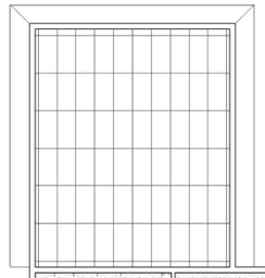
Garage Ceiling Placed
-
Pick on one of the vertical grid lines.
- Click on the Move tool and move the grid line 1′-0″ to the right. This will center the panels so that the lights will also be centered in the garage.
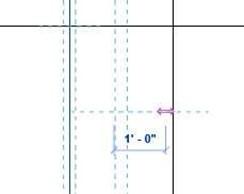
Moving the Grid Line
Creating the Second Floor Ceilings
- Switch to the Second Floor ceiling plan view.
Turn off the exterior and interior elevation marks.
-
Select the interior walls and change the height of the walls to 8′-1″.
-
Click on the Ceiling tool, set the ceiling type to the GCB – 5/8″ type. Set the height of the ceiling to 8′-0″.
Add the ceilings as shown.
-
There will be a total of nine ceilings.
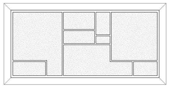
Second Floor Ceilings Placed
Next, you will create another ceiling type. This type will represent the ceiling joists, these joists will rest on top of the top plate of the wall.
- Create a new ceiling type called Ceiling Joists – 2×6.
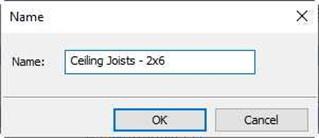
New Ceiling Type
- Add the layers as shown.
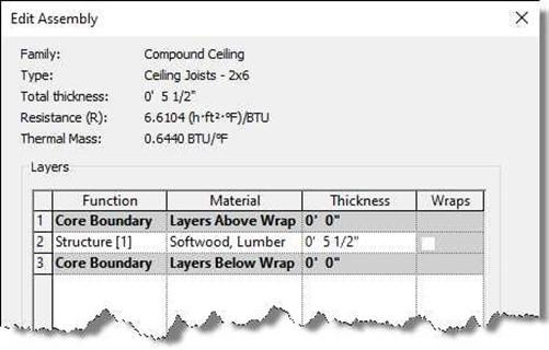
Ceiling Structure
- When placing the ceiling boundary, set the offset to – 0 – 1 1/4″.
Use the Pick Walls option and select the outside edge of the walls.
Set the level to Plate line and the Height Offset From Level to 0′-0″ in the Properties dialog.
- Open the Second Floor view.
- Create a section view through the house.
Use the View, Section Tool in the Create panel.
Boundary Line
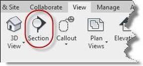 Section Tool
- Draw the section line from the left to the right through the house.
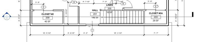
Section Line Through House
- Open the section view by double-clicking on the Section 1 in the Project Browser.
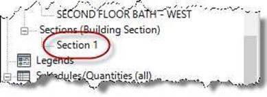
New Section View in Project Browser
- Zoom in on the top right side of the house. You will see there is a space between the ceiling and the bottom of the ceiling joists.
To compensate for this, you will lower the second floor plate line to 17′- 0″.
Note: The ceiling will overlap with the ceiling joists. Lower the ceiling so that it is below the bottom of the joists. You may use the Align tool to do this.
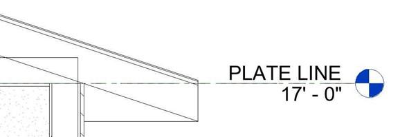
Plate Line Lowered to 17′-0″
- Open the second floor ceiling view.
If you do not see the ceilings, open the View Range dialog and increase the view depth to
1′-0″ and the top offset to 1′-0″.
Select the other eight ceilings and
lower them to 7′-11 3/8″.
Do not change the Ceiling Joist ceiling when doing this. To avoid doing this draw the fence along the middle of the exterior walls.
Note: You can also set the ceiling height level to Plate Line and the Height Offset From Level setting to – 0′ 5/8″. Then, if you change the plate line to a different height the ceiling will adjust as well.
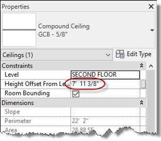
New Height Setting for Ceilings
- To make the section accurate, also change the second floor interior walls to a top constraint of Plate Line.
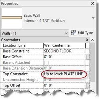
Wall Top Constraint Setting
- This is the end of Part 2. Save your file as RL5-2.
![AutoCAD shortcuts & hotkey guide [All]](https://civilmdc.com/learn/wp-content/uploads/2020/06/AutoCAD-Shortcut-keys-scaled-e1591837739256-931x1024.jpg)