Locating the Building, Adding the Exterior Walls and the
First Floor Interior Walls
In this part you will locate the building on the site, create the building shell and add the interior walls to the building.
- Open the RL1-1 file. Save the file as RL1-2.
- In the Project Browser, switch to the First Floor view.
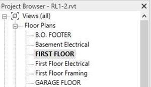
First Floor View
- Click on the Light Bulb at the bottom of the view. This is used to Hide or Display elements of the drawing.
- You will see a magenta symbol in the middle of the screen and a symbol with two arrows.
The color indicates that these are hidden elements. Select the elements by drawing a fence around them, right-click, select Unhide in View, and then Category.

Reveal Hidden Elements Tool

Unhide the Category
- You will not see the Internal Origin appear when you unhide the other elements.
To unhide it, open the Visibility Graphics Overrides dialog box by clicking the Edit… button in the Properties dialog box.
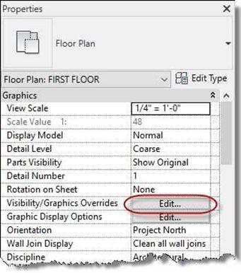
Visibility Graphics Overrides Edit… Button
-
You will not be able to move the Internal Origin.
According to Autodesk…
“The internal origin is the starting point for the internal coordinate system, which provides the basis for positioning all elements in the model.”
Note: During the course of the project, you should leave the Internal Origin off.

Internal Origin
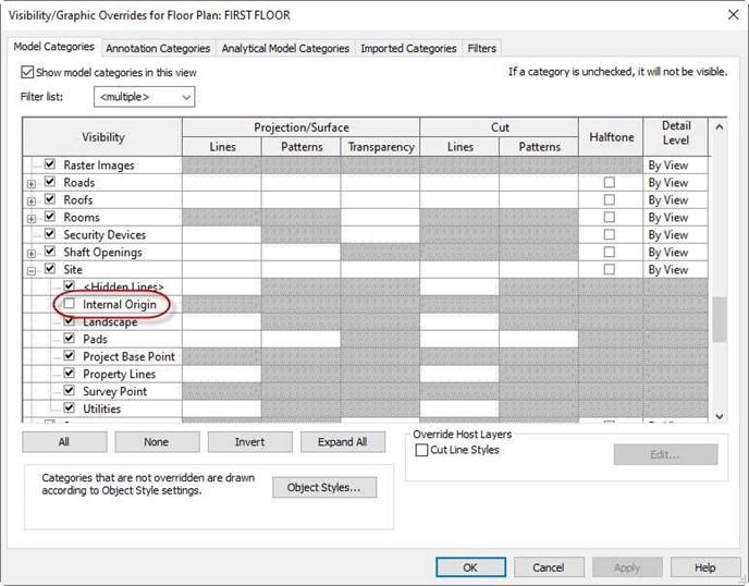
Visibility/Graphic Overrides
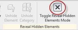 The elements will turn gray. Click on the Light bulb icon to turn off the Reveal Hidden Elements mode.
You may also click on the Toggle Reveal Hidden Elements Mode tool art the upper left corner off the screen.
- The elements that you revealed are used to mark the project base point.
Click on the center of the element to see the location of the mark.
When you start the walls, you will do so in relation to this point. The lower left corner of the property line will be placed later at this base point.

Project Base Point
- The house will be drawn on top of the Internal point.
You will locate the base and survey points approximately 62′-0″ south and 32′-0″ west from the internal point.
You may use reference planes to locate the two points.
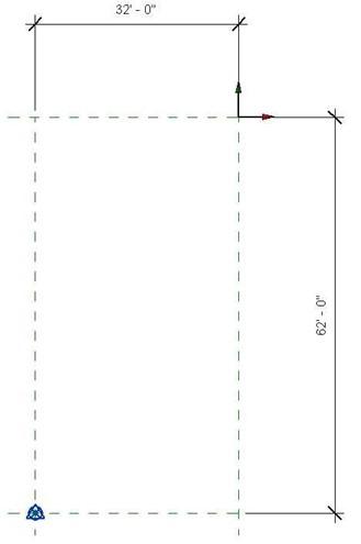
Toggle Reveal Hidden Elements Mode Tool
 Now you will begin drawing the external walls for the house. Select the Wall tool from the Architectural ribbon, Build panel. All walls will be drawn to their default height of 20′-0″.
Wall Tool
-
In the Type Selector, select Basic Wall Exterior
–Wood Siding on Wood Stud.
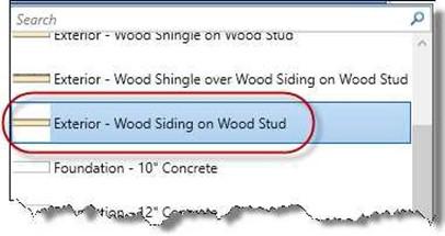
Exterior – Wood Siding on Wood Stud
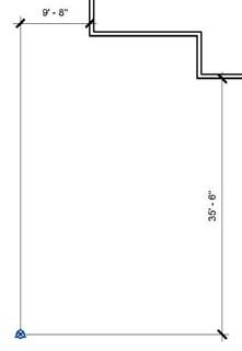
- Based on the drawing, draw the exterior walls to the locations shown.
Position the exterior walls so that the bottom of the building is 35′-6″ and the left side is 9′-8″ from the Base Point.
Measure the distance from the center of the Base Point to the exterior face of the walls.
You may use Reference Planes to help with this process.
Location of Building From Base Point
- Once the walls are drawn, select the base point and right-click on it.
- Select the Category option in the Hide in View command. You need to do this for the base point and survey point.
After hiding both parts of the Base Point, the dimensions will also hide.

Hide in View (Category)
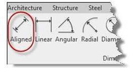 After completing the exterior walls, dimension the locations.
Use the Aligned Dimension tool in the Dimension panel.
Aligned Dimension Tool
- The exterior walls are to be dimensioned to the face of core and the interior walls to the center unless shown otherwise. Use the Faces of Core option in the option bar when placing the dimensions. To see the individual layers of the walls, use the Thin Lines toggle in the Quick Access Toolbar.

Faces of Core Option

Thin Lines Toggle
- When placing the dimensions. Set the Detail Level to Fine.
This will help to show the core boundary of the wall.
When adjusting the locations of the walls, do not move the south and east walls.
You may also set the scale of the view to 1/8″ = 1′-0″ to see the dimension text clearly.

Detail Level Set to Fine
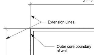
Extension Line Locations
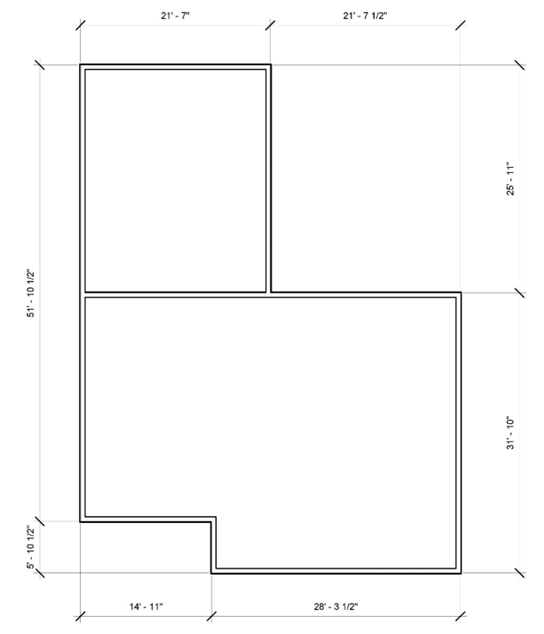
Exterior Wall Dimensions
- Next, you will need to move the elevation markers slightly so that they are around the outside edges of the walls. Select all four elevation markers. You may need to select them separately and hold the CTRL key until all markers are selected.
- Click on the Move tool in the Modify panel.
- Drag the mouse to the center of the walls and release the button. Position the markers as shown. Also, the scale has been changed to 1/8″ = 1′-0″ to show the text.
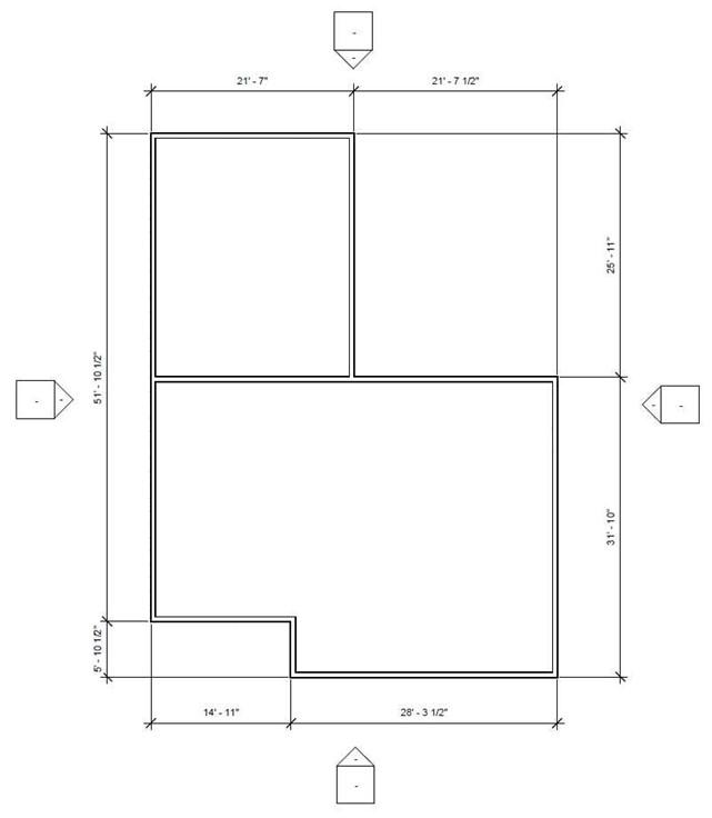
Markers Repositioned
- Add the interior walls as shown. Change the type of wall in the Properties palette using the Type Selector. Do not include the text notes identifying the wall types.
Use the Align tool to align the two walls for the Kitchen and the wall at the south corner as noted. When aligning the walls, click the padlock so that the alignment remains permanent.
Note: The dimensions for the walls will change as you progress through the project. Your dimensions may be different than the ones shown in the example.
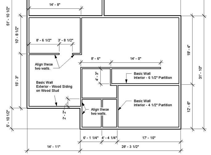
First Floor Interior Wall Dimensions
-
You may notice that the Basic Wall Interior – 6 ½” Partition wall has seam lines at both ends. This is due to the core material being Metal Stud rather than Softwood Lumber. Click on the wall to change its properties.

Seam Lines
- Click on the Edit Type button to open the Type Properties dialog box for the wall.
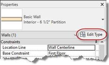
Edit Type Button
- In the Type Properties dialog box, click on the Edit… Button next to the
Structure parameter.
- In the Edit Assembly dialog box, select the Metal Stud Layer material and then click the small box that appears next to the name of the material.
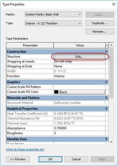
Type Properties Dialog Box
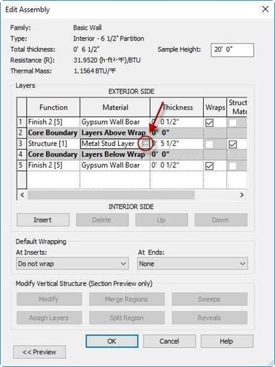
Edit Assembly Dialog Box
- The Material Browser dialog box opens. Search for the Softwood Lumber material in the search box at the top left. Select the material and click OK.
Note: If the library panel at the bottom left is not showing, click on the double arrows next to Material Libraries. To expand the dialog box to show the Material Editor, click on the double arrows at the bottom of the dialog box.
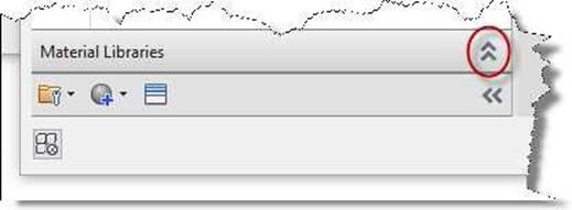
Shows/Hides Library Panel Tool
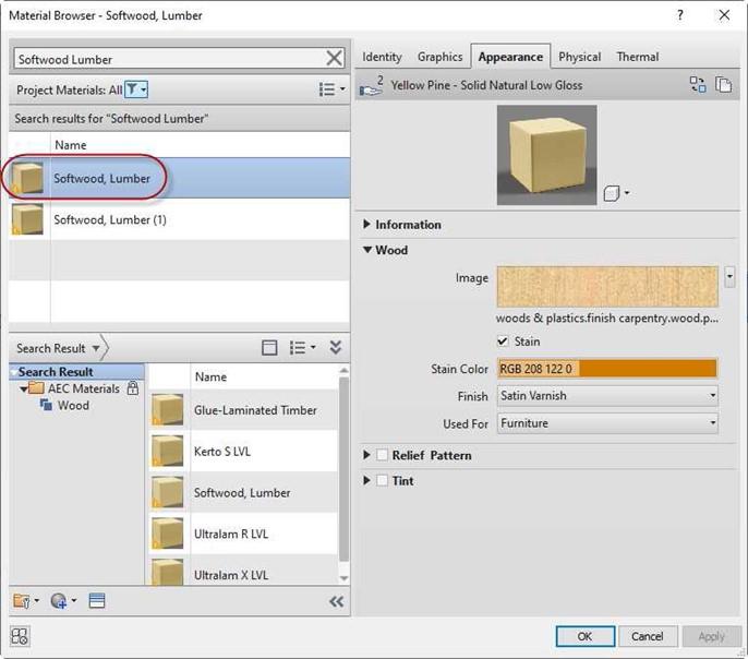
Material Browser Dialog Box
 Click OK in each of the dialog boxes to end the command. The seam lines at each end of the wall are now gone.
Seam Lines Removed
- This is the end of Part 2. Save your file as RL1-2.


![AutoCAD shortcuts & hotkey guide [All]](https://civilmdc.com/learn/wp-content/uploads/2020/06/AutoCAD-Shortcut-keys-scaled-e1591837739256-931x1024.jpg)
