Creating the First Floor, Garage Floor, Porch, and Driveway Slabs
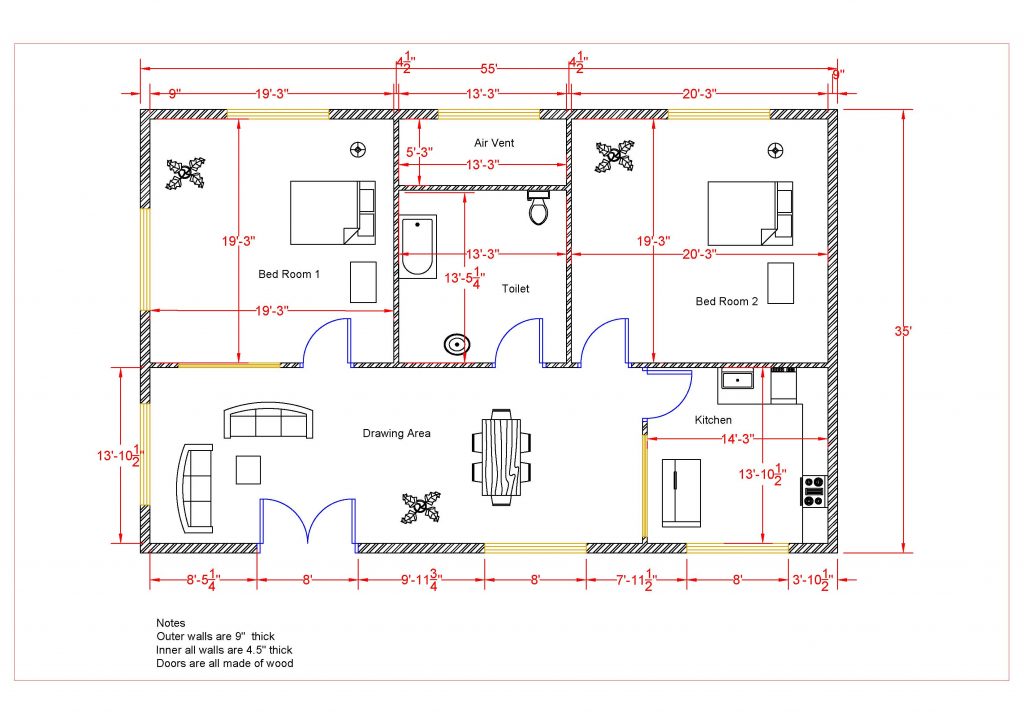
In this tutorial you will add four floor slabs to the project. This will provide a floor surface for the walls, fixtures, and furniture on the first floor. You will also use the Extrusion tool to create a thickened portion for the Garage slab. This project is a slab-on-grade foundation so there will not be a crawl space under the floor.
Adding the Main House Slab
- Open the RL1-7 file. Save the file as RL1-8.
- Open the First Floor view.
- Select the Floor tool located in the Architecture tab, Build panel.
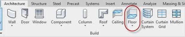
Floor Tool
- In the Type Selector select the Concrete Slab – 4″.
- Duplicate the type and name it Concrete Slab – 4″ w/Carpet.
- Edit the structure.
Add a 1/8″ layer of carpet to the top level as shown.
Modify the Carpet (1) material so that the surface pattern is light gray (RGB 192 192 192).
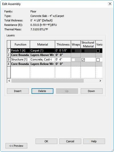
Edit Assembly for New Slab Type
- Press OK twice to close the dialog boxes.
- Zoom in on the floor area of the house.
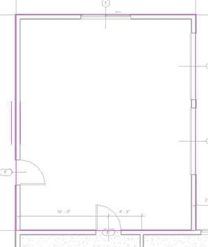
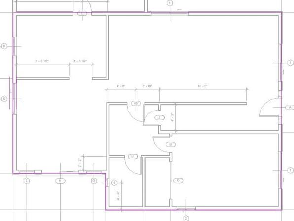 Use the Pick Walls option to add the floor boundary to the walls. The boundary will be to the outside face of the core.
Sketch Boundary for First Floor Slab
- Click the Green Check to place the slab.
- Switch to the 3D view to view the slab.
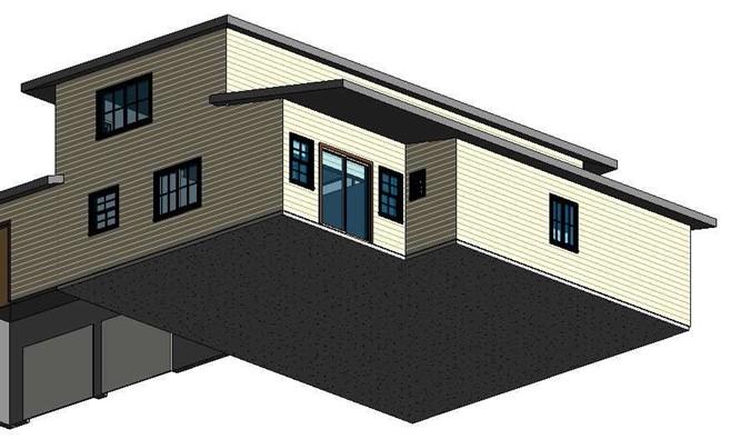
First Floor Slab
- Switch back to the First Floor view.
Adding the Garage Slab
- Zoom in to the Garage area.
- Pick the Floor tool.
Pick the Concrete Slab – 4″ type.
- Duplicate the slab type and name it Concrete Slab – 6″.
- Click the Edit… button next to Structure and change the thickness to 6″.
Modify the “Concrete, Cast-in-Place gray” material so that the surface pattern
is gray (Color 192).
Click OK to implement the changes to the new floor type.
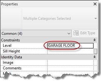
- Set the Level to Garage Floor.
- Click the Edit Type button.
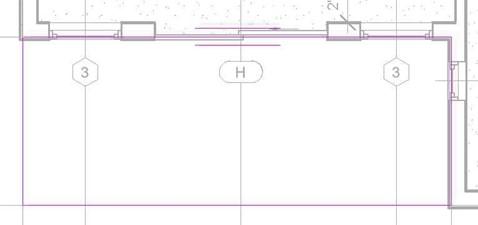
- Create the boundary as shown.
Use the Pick Lines option for the south edge of the garage. The line that you will pick is the edge of the house slab.
Trim/Extend the lines to make a closed shape.
Click the Green Check.
Garage Slab Sketch Boundary
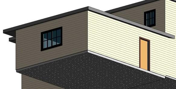
- Switch to the 3D view. You should notice a gap between the bottom on the garage walls and the top of the slab.
Garage Walls Not Attached
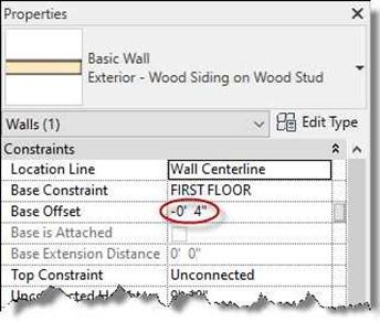
- Rotate the 3D view and pick the three garage walls.
-
In the Properties box, change the Base Offset to
-0′-4″.
-
The bottoms of the three walls are now touching the Garage Floor level.
The reason that the base constraint was not set to Garage Floor is that the siding pattern would not match with the walls of the house.
- Pick the three doors and the one window.
Set the level to Garage Floor. Click the Apply button.
The door and windows are now set to the Garage Floor level.
Base Offset Changed to -0′-4″
Level Changed to Garage Floor
Walls Attached, Doors and Window Adjusted
Adding the Porch Slab
- Switch back to the First Floor view.
- Zoom in to the Porch area at the bottom left corner of the plan.
- Click on the Floor tool and select Concrete Slab – 4″.
- Set the Height Offset From Level to -0′ 0 1/2″.
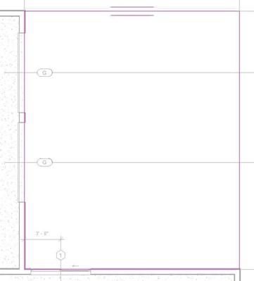
- Create the boundary as shown.
Pick the outside face of core of the four walls on the corner and then use the Trim/Extend tool to create the rectangular slab.
Click the Green Check to place the slab.
Porch Slab Sketch Boundary
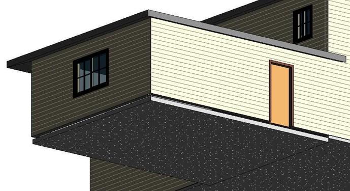
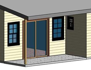
- Switch to the 3D view. The porch slab should look like this.
Note: To see the trim around the sliding glass door you will need to set the Detail Level to Fine.
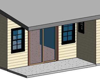
Completed Porch Slab
Adding the 4×4 Post at the Corner of the Porch Area
- Switch to the First Floor view. Zoom in on the porch area.
- Click on the Column tool in the Architecture tab, Build panel.
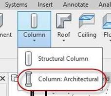
Column: Architectural Tool
- Select the Wood Timber Column 5 x 5 in the Properties Box Type Selector.
- Click the Edit Type button.
- Duplicate the family and rename it 4 x 4.
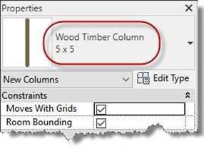
Wood Timber Column 5 x 5
- In the Properties dialog change the Depth and Width to 3 1/2″.
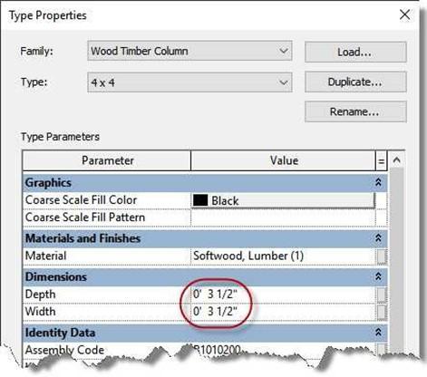
New Wood Timber Settings
- Position the post as shown.
The dimensions should be deleted or hidden after placing the column.
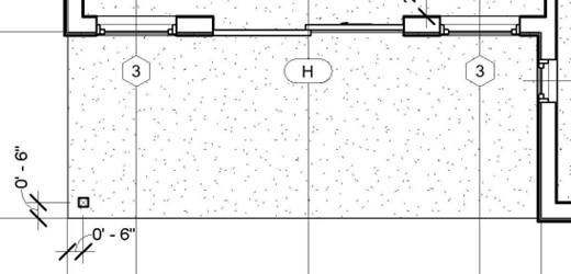
4 x 4 Post Added
- Switch to the 3D view.
- The top of the post is slightly below the bottom of the roof.
Click on the post, and then click on Attach Top/Base.
- Click on the Roof.
- The post is now attached.
Adding the Driveway Slab
- Open the First Floor view.
- Using the Concrete Slab – 6″ type, create a slab for the driveway as shown.
You will only be adding the slab in the area shown. The rest of the driveway will be added later.
4 x 4 Post Attached to Roof
Sketch Boundary of the Driveway Slab
- When creating the boundary pick the face of core for the four walls
For the other two edges match with the edges of the First Floor slab.
- Set the level of the slab to Garage Floor.
Be sure to set the Height Offset from Level parameter back to 0′-0″.
Click the Green Check to place the slab.
- Switch to the 3D view to check the placement of the slab.
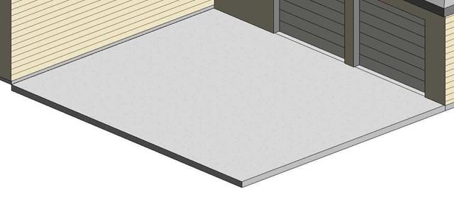
Driveway Slab Placed
Changing the Color of the Window Frame
- While working through the project you may have noticed that the frames of the windows are colored black. This does not match with the rendered appearance of the window. While you may not have rendered the exterior of the house by this point, you might have noticed the Realistic and Ray Trace modes in the Visual Style tool.
- If you switch to the Realistic mode, the window frames material will appear to be white instead of black. In these next few steps you will change the material color in the Shaded mode to match the material in Realistic mode.
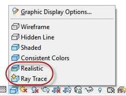
Realistic and Ray Trace Visual Styles
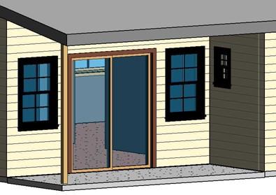
Rear Porch in Shaded Mode
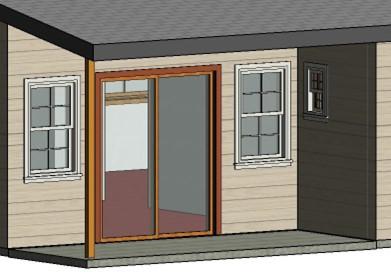
Rear Porch Area in Realistic Mode
- Open the 3D view of your project and click on one of the Double Hung windows.
-
In the Properties Box, click on the Edit Type button.
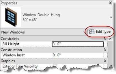
Edit Type Button
- In the Type Properties dialog box, scroll down to the Materials and Finishes area. This will show the materials for the Exterior Frame and other parts of the window.
The material that you will change is the Clad – White material.
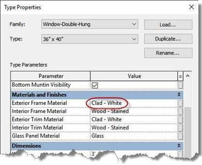
Type Properties Dialog Box
 Click on the material and then the small box to the right. This will open the Materials Dialog box.
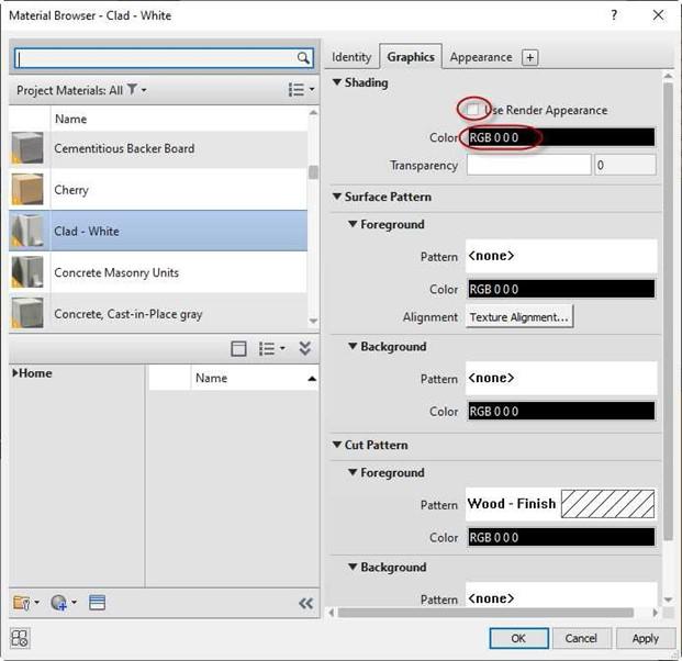
Material Browser Dialog Box
- Uncheck the Use Render Appearance checkbox.
Click on the Color bar in the Shading area. Change the material to color RGB 216 216 204.
This will change the all the windows to light gray for the frame and trim material.
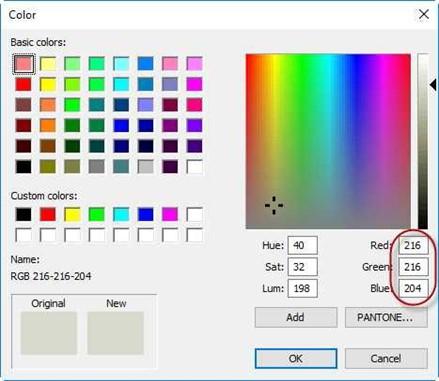
Color Dialog Box
- Click OK to close the Color dialog box. Click OK in the Material Browser dialog box to close and apply the changes.
- The frame and exterior trim of all the windows are now light gray.
- This is the end of Part 8. Save your file as RL1-8.
![AutoCAD shortcuts & hotkey guide [All]](https://civilmdc.com/learn/wp-content/uploads/2020/06/AutoCAD-Shortcut-keys-scaled-e1591837739256-931x1024.jpg)