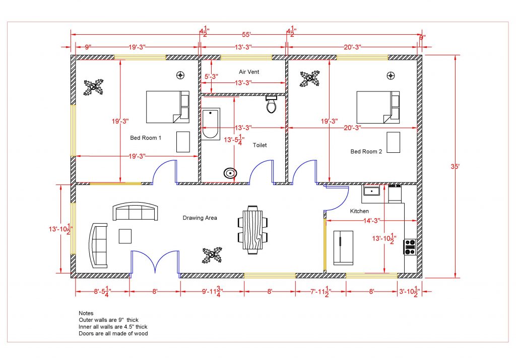
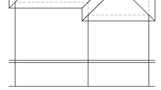
Adding the Roof Edges, Projecting the Front Elevation View
- Open the WU3-1 file. Save the file as WU3-2.
- Continuing from the Part 1, add the lines for the Roof Edges. The lines will either be drawn as horizontal, vertical, or at a 45-degree angle. Start by adding the angled lines at each corner.
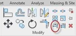
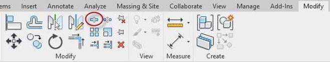
- When adding the lines, try using the Copy tool in the Modify panel.
Note: The dimensions have been hidden for clarity.
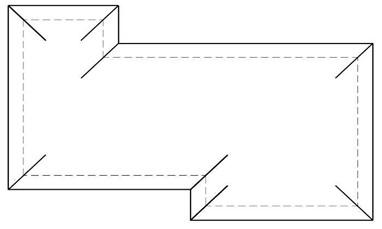
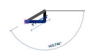
Angled Lines Added
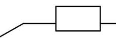
Degree Angle Line
-
Use the
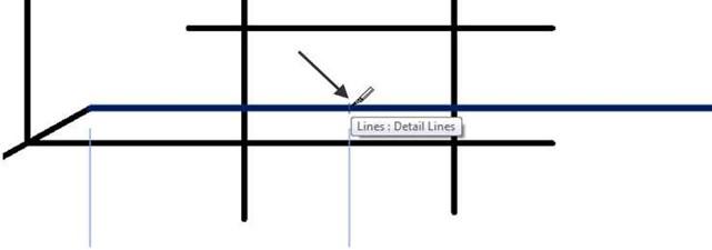
Trim/Extend tool to join the lines as shown in these steps.
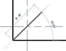
Sequence for Adding the Roof Edges (Read Left to Right)
- Add the chimney as shown. Use the Line, Offset, and the Trim/Extend tools.
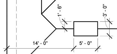
Leave the dimensions for later.
If you do not have all of the dimensions, you will add them
in Part 3.
Chimney Location
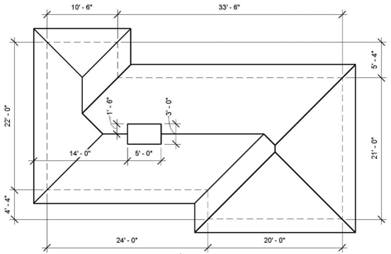
Plan View with Dimensions
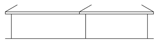
Adding the Front Elevation
Next you will add the Front Elevation by projecting from the plan view. This is the completed Front Elevation. Add the dimensions to help locate and verify the size of elements.
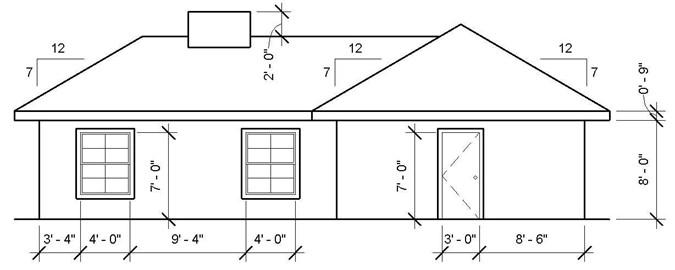
Completed Front Elevation
- Add the ground line first. Start the line approximately 22′-0″ from the bottom edge of the plan view.
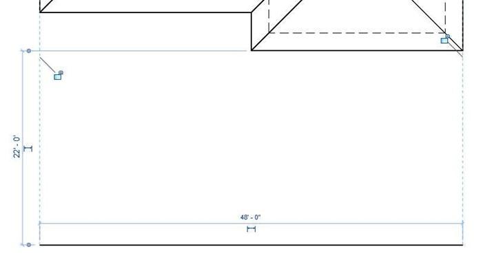
Ground Line Location and Length
- Project the wall lines and offset the ground line for the fascia board
Wall Lines Projected and Ground Line Offset
- Add two vertical lines for the edge of the fascia.
Trim the wall lines using the Trim/Extend Single Element tool.
Begin the trim by clicking on the bottom fascia line and then the portion of the wall line below the fascia line. You could also use the Trim/Extend Multiple Elements tool.
 Trim/Extend Single Element Tool
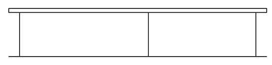
- Draw the roof slope lines.
Wall Lines Trimmed
The slope is 7:12. Add the first line by drawing a 12″ horizontal and then a 7″
vertical line. After that, connect the lines to make the diagonal slope line.
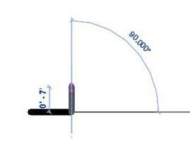
Horizontal And Vertical Lines Sloped Line
 Copy the only sloped line from the triangle to the corners of the fascia board. You can use the Mirror tool for the sloped line on the far right of the roof.
Sloped Lines Added
- Project the ridge of the roof and trim/extend the sloped lines.
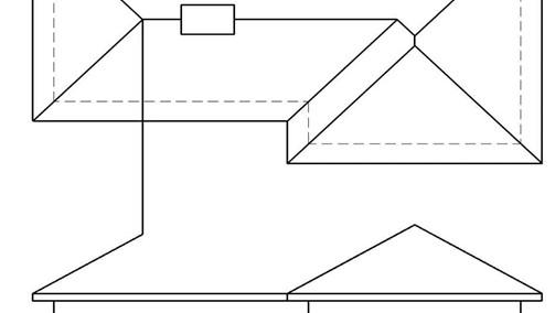
Projecting the Ridge and Extending the Sloped Lines
- Project the edges of the chimney and locate the bottom edge by projecting as shown.
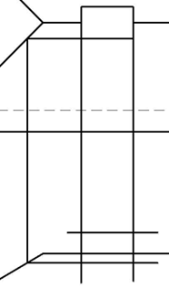
Chimney Edges Projected
- Trim the edges of the chimney. You will need to use the split tool to split the ridge line for the chimney edges.
Split Tool
Split Location
- Trim/Extend the lines to form the chimney.
Chimney Completed
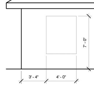
Adding the Windows
Use the diagram below for the sizes of the windows. Refer to the Front Elevation for the locations of the two windows. You may add dimensions to help with the sizes. Delete the dimensions after completing the window, they will not be needed.
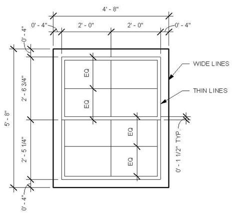
Window Dimensions
- When adding the windows to the elevation view, begin by placing the outside edge of the window (not the trim) on the elevation first.
Inner Window Outline Added
- Use the Offset tool to add the wide lines for the trim around the outside edge.
- Add the remaining lines to the window
- Once the window is added, you will use the Copy tool to copy the window to the second location.
- Click on the Modify tool on the upper right corner of the screen. Select the window. The window will turn blue.
- Click on the Copy tool in the Modify panel.
- Click a point near the window. Drag to the right.
Type in the distance 13 4 (13′-4″) and click the mouse a second time to place the copy.
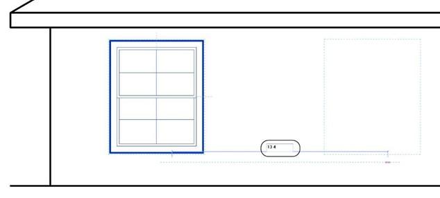
Copying the Window 13′-4″ to the Right
- Next you will add the Front Door.
Use the diagram below for sizes. Refer to the front elevation drawing for the location.
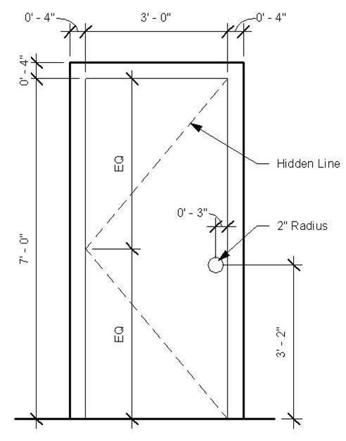
Door Dimensions
- This is the end of Part 2. Save your file as WU3-2.
![AutoCAD shortcuts & hotkey guide [All]](https://civilmdc.com/learn/wp-content/uploads/2020/06/AutoCAD-Shortcut-keys-scaled-e1591837739256-931x1024.jpg)