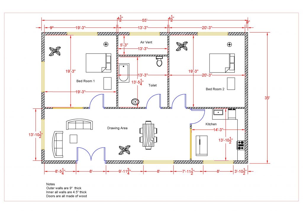
Adding the First Floor Doors and Windows
Now that you have added the walls you will now place the doors and windows for the building.
Adding the Windows
- Open the RL1-2 file. Save the file as RL1-3.
- Continue in the First Floor view.
- Select the Window tool from the Architectural ribbon, Build panel.

Window Tool
- In the Type Selector, select the window based on the table and floor plan example shown later in this tutorial part. The door and window tags are for reference only. You be adding tags to your project later in the tutorial.
- After adding the windows, dimension their locations as shown. Add missing dimensions using the Edit Witness Lines Tool. This tool is accessible by clicking on one of the dimensions on the drawing.
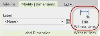
Edit Witness Lines Tool
- After adding the windows, the dimension may not activate (turn blue) after clicking on the element. To activate the dimensions, click on the Active Dimensions button in the Options Bar.

Activate Dimensions Button
-
The Window-Sliding-Double window family is not loaded with the template file. Before you can add this window you will need to load the family.
Click on the Window tool in the Architecture tab, Build panel.

Window Tool
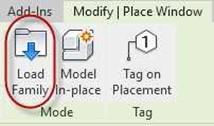 Click on the Load Family tool. The Load Family dialog will open.
Scroll down to the Windows folder at the bottom of the folders.
Load Family Tool
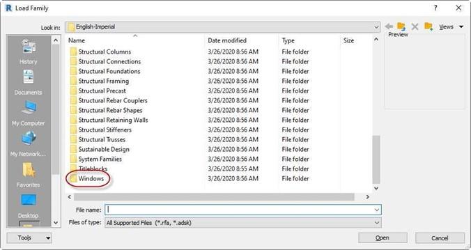
Load Family Dialog
- Open the Windows folder and select the Window-Sliding-Double Family file.
Click the Open button in the dialog box to load the family and close the dialog.
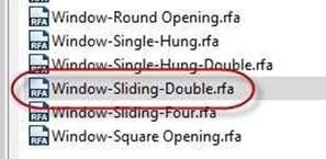
Window-Sliding-Double Family File
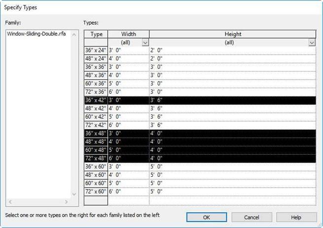
- When loading the window family, you will be asked to select the individual types. Refer to this chart for the sizes to be loaded.
- After loading the types, click on the Type Selector to choose the type needed.
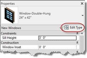 The Window-Double-Hung type is preloaded with the template file.
All the sizes for the project will need to be created.
Use the Edit Type button to open the Type Properties dialog box to create the custom sizes.
Edit Type Button
- Click the Duplicate button to create a new Double Hung window type.
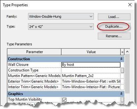
-
Create a new window type called
16″ x 24″.
Note: The first value represents the width and the second is the height.
- Change the size of the window in the Type Properties dialog box in the Dimensions area.
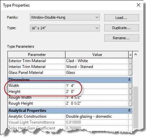
Type Properties Dialog Box
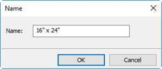
New Window Type
- Load/create the window types as shown in the table.
The name of the window type shows the width of the window first and then the height.
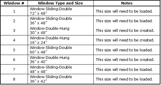 The Window # column is to identify the window on the plan view.
Window Size Changed
- After placing Window #4 in the Bathroom click on the window and set the Head Height to 7′-0″.
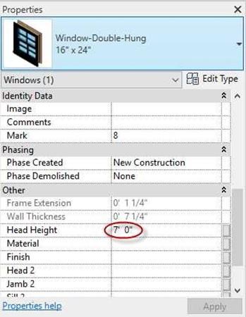
Change Head Height to 7′-0″
Adding the Doors
Next you will add the doors to the first floor.
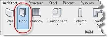 Select the Door tool from the Architectural ribbon, Build panel.
Door Tool
-
In the Type Selector, select the door based on the chart below:
(Some families will need to be loaded from the Doors folder in the US Imperial folder on the hard drive.)
Note: You may decide to letter the doors differently than as shown in the example.
|
Door Letter |
Door Type and Size |
Notes |
|
A |
Single-Raised Panel with Sidelights 36″ x 84″ |
Size is included. |
|
B |
Single-Flush 32″ x 80″ |
This size will need to be created. |
|
C |
Single-Flush 34″ x 80″ |
Size is included. |
|
D |
Sliding-Closet 72″ x 80″ |
Size is included. |
|
E |
Single-Flush 36″ x 80″ |
Size is included. |
|
F |
Single-Flush 36″ x 84″ |
Size is included. |
|
G |
Door-Overhead-Sectional 8′ x 6′-6″ |
Family will need to be loaded from Doors Folder. Size is included. |
|
H |
Door-Double-Sliding 72″ x 84″ |
Family will need to be loaded from Doors Folder. Pick size. |
|
J |
Single-Flush 30″ x 80″ |
Size is included. |
-
When loading the Sliding Glass door, you will need to select the 72″ x 84″ size
in the Specify Types dialog.
This will be the only size that you will need for the project.
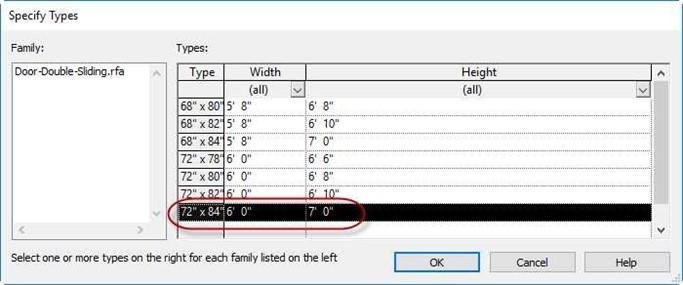
Specify Types Dialog Box
- After adding the doors, dimension their locations as shown on the next page.
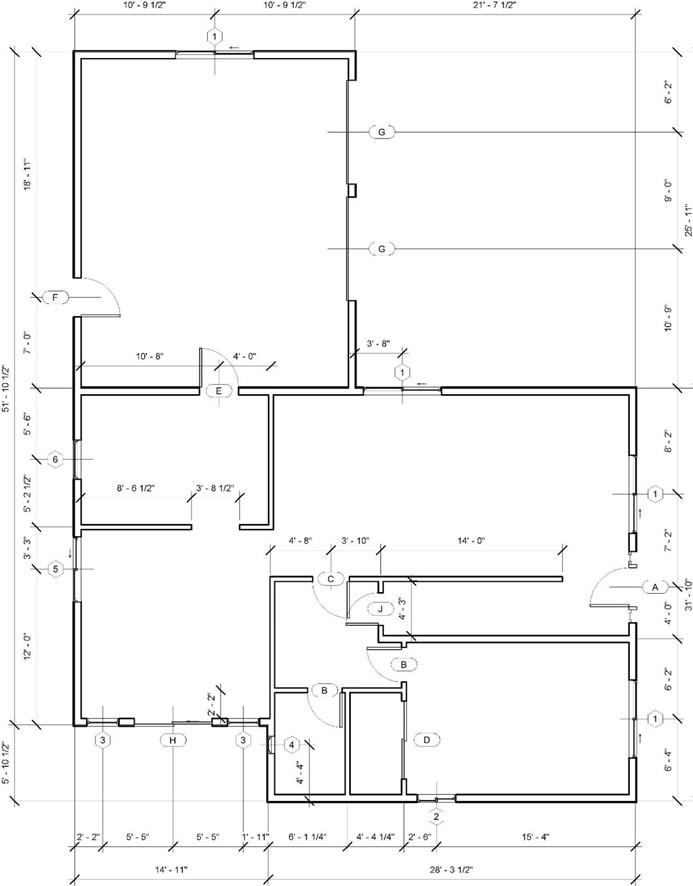
First Floor Door and Window Locations
- Scan the drawing for missing dimensions. If you find any, click on the dimension line and select the Edit Witness Lines tool in the Witness Lines panel.
To add dimensions to the existing chain, click on the element to dimension. When finished, click in open space.
- This is the end of Part 3. Save your file as RL1-3.


![AutoCAD shortcuts & hotkey guide [All]](https://civilmdc.com/learn/wp-content/uploads/2020/06/AutoCAD-Shortcut-keys-scaled-e1591837739256-931x1024.jpg)
