Editing the External References
AutoCAD allows you to edit the external references in the file to which they are attached. You can
also edit them by opening their drawing file. The procedure to edit an external reference is discussed next.
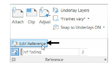
To edit an external reference, expand the Reference panel and click the Edit Reference button.
Select Nut from the drawing; the Reference Edit dialog box appears
Click OK to get into the reference editing mode.
In the drawing, you will notice that the centerlines of the nut are overlapping on the
centerlines of the crank. Delete the centerlines and center marks of the nut.
Click Save changes on the Edit Reference panel; the AutoCAD message box appears.

Click OK.
Adding Balloons
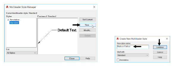
Click Annotate > Leader > Multileader Style Manager (inclined arrow) button on the ribbon;
the Multileader Style Manager dialog box appears.
Click the New button on the dialog box.
In the Create New Multileader Style dialog box, enter Balloon Callout in the New Style
name box and click Continue.
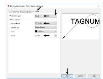
In the Modify Multileader Style dialog box, click the Content tab and set the Multileader type to
Block.
Under Block Options, set the Source block to Circle.
Set the Scale to 3.
Click Leader Format tab and set the Arrowhead Size to 8.
Click OK and set the Balloon Callout style as current, as shown.
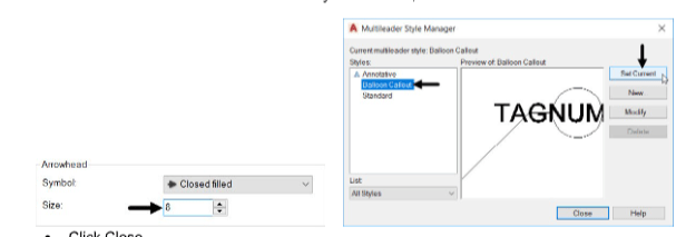
Click Close.
Click Annotate > Leader > Multileader on the ribbon.
Click the down arrow next to the Polar Tracking button on the status bar and select 45 from the menu.
Activate the Polar Tracking.
Select a point on the section view of the crank.
Move the cursor along the polar trace lines and click; the Edit Attributes dialog box appears.
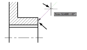
In the Edit Attributes dialog box, enter 1 in the Enter tag number field.

Click OK; the balloon will be created.
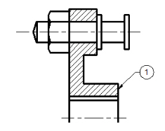
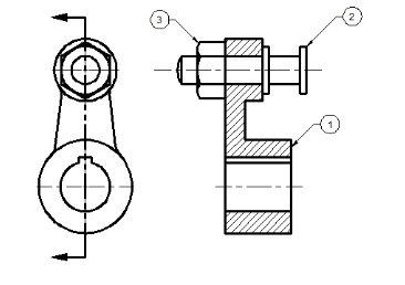
Similarly, create other balloons.
Creating Part List
Click Annotate > Table > Table Style on the ribbon; the Table Style dialog box appears.

In the Table Style dialog box, click the New button; the Create New Table Style dialog box appears.
In the Create New Table Style dialog, enter Part List in the Name box. Click Continue; the New Table Style dialog box appears.
Click the Text tab and set the Text height to 10, as shown.
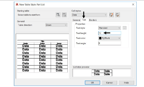
Select the Header option from the Cell Styles drop-down and set the Text height to 10.

Click OK.
In the Table Style dialog box, select the Part List style and click Set current.
Close the dialog box.
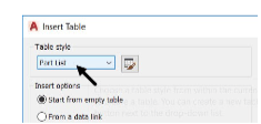
Click the Table button on the Tables panel; the Insert table dialog box appears.

Ensure that the Table style is set Part List.
Under the Set cell styles group, set the First row cell style to Header.
Set the Second row cell style and All other row cell styles to Data.

Set the number of Columns to 4 and Column width to 65 and fill other entries, as shown.

Click OK and place the table at the lower right corner of the drawing window.
Enter PART No., NAME, MATERIAL, QTY in the first row of the Part list table. Use the
TAB key to navigate between the cells.
Click Close Text Editor button on the ribbon.

Click on anyone of the edges of the table; you will notice that grips are displayed on it. You can edit the table using these grips.

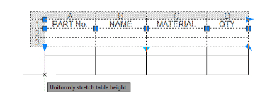
Click and drag the square grip below the MATERIAL; the width of the cell will be changed.

Click and drag the triangular grip located at the bottom left corner of the table; the height of the rows will be increased uniformly.
Click in the second cell of the first column; the Table Cell ribbon appears. You can use this ribbon to modify the properties of the table cell.

Click the Insert Below button on the Rows panel; a new row will be added to the cell.

Click in the top left corner cell of the table.
Press and hold the SHIFT key and click in the lower right corner of the table; all the cells in the table will be selected.
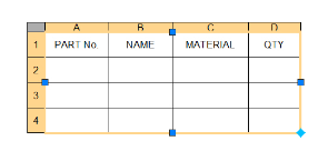
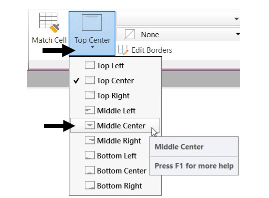
In the Table Cell ribbon, click Cell Styles > Alignment > Middle Center; the data in all the cells will appear in the middle center of the cells.
Double-click in the cell below the PART No.; the text editor will be activated.
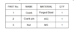
Enter the following data in the cells. Use the TAB to navigate between the cells.
