Creating Orthographic Views
Orthographic Views are standard representations of an object on a drawing sheet. It is the method to
generate information related all the hidden and visible features of an object. These views are
generated by projecting an object onto three different planes (top plane, front plane, and side plane).
These three views are projected and aligned with each other. You can project an object by using two
different methods:
– First Angle Projection
– Third Angle Projection.
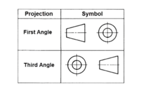
First Angle Projection
Orthographic views created while projecting an object using the First Angle Projection method.
The object is kept in the first quadrant.
The object lies between the observer and plane of projection.
The plane of projection is assumed to be non-transparent.
When views are drawn in their relative position; Top view comes below Front View and
Right View drawn to the left side of the elevation.
Note: In AutoCAD, you can generate these projection view by activating the ORTHO mode, by
pressing the F8 key. The projected lines are either horizontal or vertical.
Below is the figure in which orthographic views are created while projecting an object using the First
Angle Projection method.
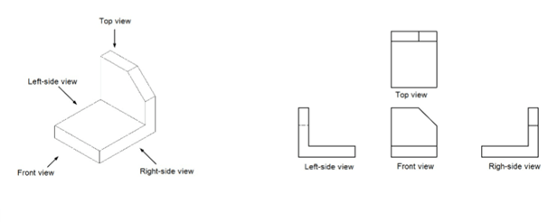
Third Angle Projection
Orthographic views created while projecting an object using the Third Angle Projection method.
The object is kept in the third quadrant.
The plane of projection lies between the observer and object.
The plane of projection is assumed to be transparent.
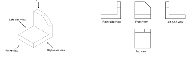
When views are drawn in their relative position, Top view comes above Front View and Right
View drawn to the right side of the elevation.
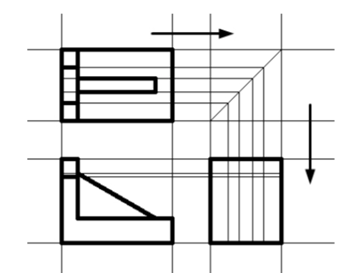
Below is the figure in which orthographic views are created while projecting an object using the Third
Angle Projection method.
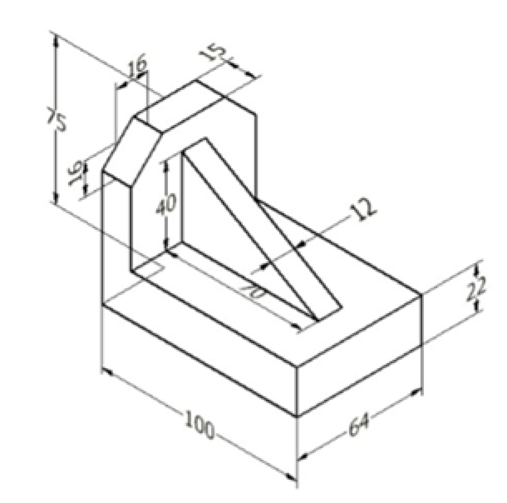
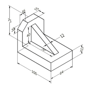
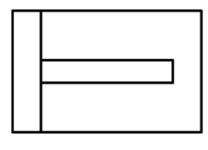
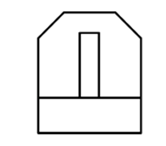
Example:
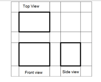
In this example, you will create the orthographic views of the part shown below. The views will be
created by using the Third Angle Projection method.
Open a new drawing.
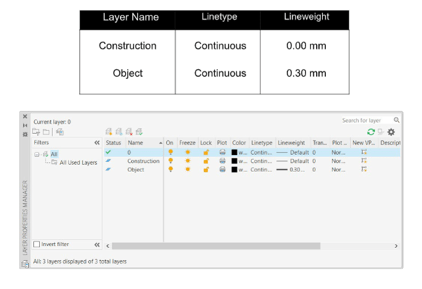
Click the Layer Properties button on the Layer panel; the Layer Properties Manager appears.
Click the New Layer button on the Layer Properties Manager to create new layers.
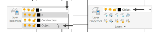
Create two new layers with the following properties.
Right-click on the Construction layer and select Set current, as shown.
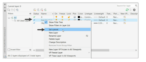
Close the Layer Properties Manager.
Activate the Ortho Mode on the status bar.
Click Zoom > Zoom All on the Navigation Bar.
Next, you need to draw construction lines. They are used as references to create actual
drawings. You will create these construction lines on the Construction layer so that you can hide
them when required.
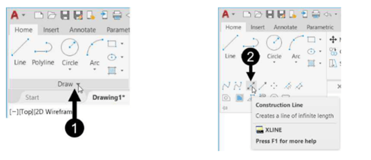
Click Home > Draw > Construction Line on the ribbon or enter XLINE in the command line.
Click anywhere in the lower left corner of the drawing window.
Move the cursor upward and click to create a vertical construction line.
Move the cursor toward right and click to create a horizontal construction line.
Press ENTER to exit the tool.
Click the Offset button on the Modify panel.
Type 100 as the offset distance and press ENTER.
Select the vertical construction line.
Move the cursor toward and click to create an offset line.
Right-click and select Enter to exit the Offset tool.
Press the SPACEBAR on the keyboard to start the Offset tool again.
Type 75 as the offset distance and press ENTER.
Select the horizontal construction line.
Move the cursor above and click to create the offset line.
Press ENTER to exit the Offset tool.
Similarly, create other offset lines as shown below.
Set the current layer to Object.
Now, you need to create object lines.
Click the Line button on the Draw panel.
Create an outline of the front view by selecting the intersection points between the construction
lines.
Right-click and select Enter to exit the Line tool.
Activate the Show/Hide Lineweight button on the status bar.
Similarly, create the outlines of the top and side views.
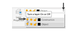
Next, you need to turn off the Construction layer.
Click on the Layer drop-down in the Layer panel.
Click the light-bulb of the Construction layer; the layer will be turned off.
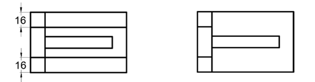
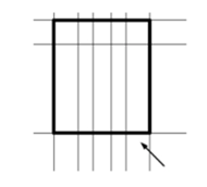
Use the Offset tool and create two parallel lines on the front view, as shown below.
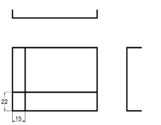
Use the Trim tool and trim the unwanted lines of the front view as shown below.
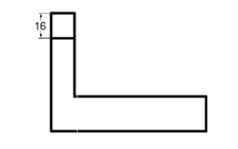
Use the Offset tool to create the parallel line as shown below.
Use the Offset tool and create offset lines in the Top view as shown below.
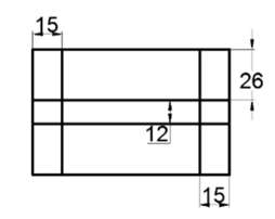
Use the Trim tool and trim the unwanted objects.
Create other offset lines and trim the unwanted portions as shown below.
Click the Line button on the Draw panel.
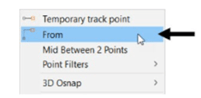
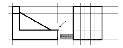
Press and hold the SHIFT key and right-click. Select the From option.
Select the endpoint of the line in the front view as shown below.
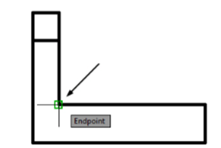
Move the cursor on the vertical line and enter 40 in the command line; the first point of the line
is specified at a point 40 mm away from the endpoint. Also, a rubber band line will be attached
to the cursor.
Move the cursor onto the endpoint on the top view as shown below.
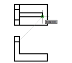
Move the cursor vertically downward; you will notice that track lines are displayed.
Move the cursor near the horizontal line of the front view and click at the intersection point as
shown below. Press ENTER to exit the tool.
Next, you need to create the right-side view. To do so, you need to draw a 45- degree miter line and
project the measurements of the top view onto the side view.
Click on the Layer drop-down in the Layer panel.
Click the light-bulb icon of the Construction layer; the Construction layer is turned on.
Select the Construction layer from the Layer drop-down to set it as the current layer.
Draw an inclined line by connecting the intersection points of the construction lines as shown
below.
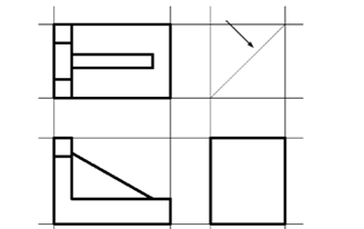
Click the Construction Line button on the Draw panel.
Select the Hor option from the command line and create the projection lines as shown below.
Right-click to exit the Construction Line tool.
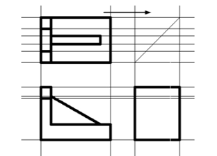
Press ENTER and select the Ver option from the command line.
Create the vertical projection lines as shown below.
Use the Trim tool trim the extend portions of the construction lines.
Set the Object layer as current.
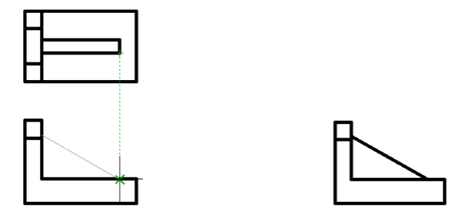
Click the Offset button on the Modify panel.
Select the Through option from the command line.
Select the lower horizontal line of the side view.
Select the end point on the front view as shown below.
Right-click and select Enter.
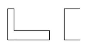
Use the Line tool and create the objects in the side view as shown below.
 Turn off the CAD Construction layer by clicking on the light-bulb of the Construction layer.
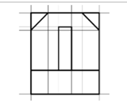
Trim the unwanted portions on the right-side view.
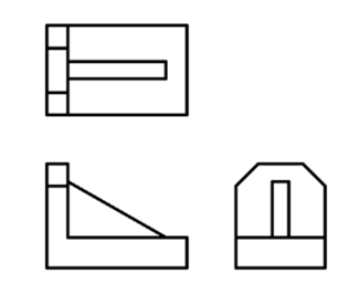
The drawing after creating all the views is shown below.
Save the file as ortho_views.dwg. Close the file.
![AutoCAD shortcuts & hotkey guide [All]](https://civilmdc.com/learn/wp-content/uploads/2020/06/AutoCAD-Shortcut-keys-scaled-e1591837739256-931x1024.jpg)