Creating Inferred Constraints
With the Infer Constraints button active at the status bar, you can automatically create constraints
while drawing a sketch.
Activate the Infer Constraints button at the status bar.

Click the Fillet button on the Modify panel of the Home ribbon.
Select the Radius option from the command line and enter 50 as the radius.
Create a fillet at the lower left corner of the sketch.
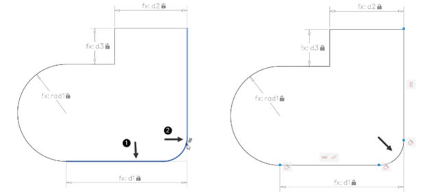
You will notice that Tangent and Coincident constraints are applied, automatically.
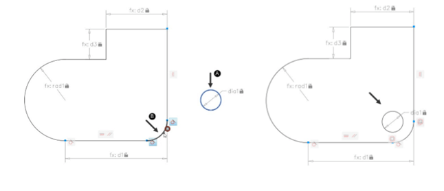
Click the Concentric button on the Geometric panel.
Select the circle located outside the loop and the fillet; they both will be concentric.
Use the Radius tool from the Dimensional panel and apply the radius dimensional
constraint to the fillet.
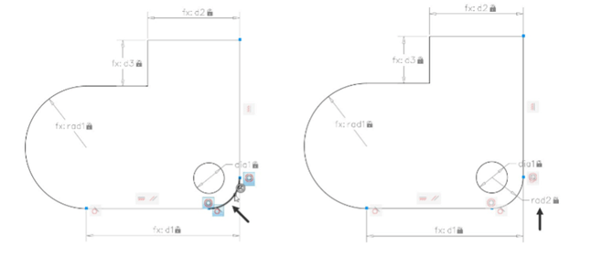
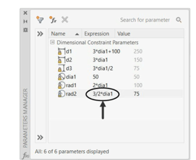
Open the Parameters Manager palette and modify the rad2 value to 3/2*dia1, as shown.
To hide all the Geometric Constraints, click the Hide All button on the Geometric panel.
Similarly, click Hide All on the Dimensional panel to hide all the dimensional constraints.
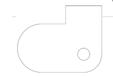
To modify the size of the drawing, change the value of dia1 in the Parameters Manager
window; you will notice that all the values will be changed, automatically.
Save and close the file.
Questions:
1. Which tool is used to make a spline continuous with another spline?
2. Which tool is used to apply constraints to the objects, automatically?
3. Which tool is used to constraint a line along another line?
4. Which tool is used to constraint a point to lie on another point or an object?
5. Where are Geometric Constraints available in AutoCAD?
Exercises
Exercise 1:
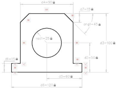
In this exercise, you need to create the drawing shown in figure and apply geometric and
dimensional constraints to it.
Exercise 2:
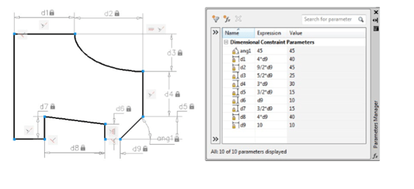
In this exercise, you need create the drawing as shown below and apply geometric and dimensional
constraints to it. Also, create relations between dimensions in the Parameter Manager.


![AutoCAD shortcuts & hotkey guide [All]](https://civilmdc.com/learn/wp-content/uploads/2020/06/AutoCAD-Shortcut-keys-scaled-e1591837739256-931x1024.jpg)
