Using the Write Block tool
Using the Write Block tool, you can create a drawing file from a block or objects. You can later insert
this drawing file as a block into another drawing. The procedure to create a drawing file using blocks
is discussed in the following example.
Example:
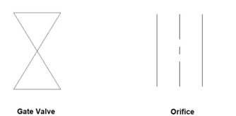
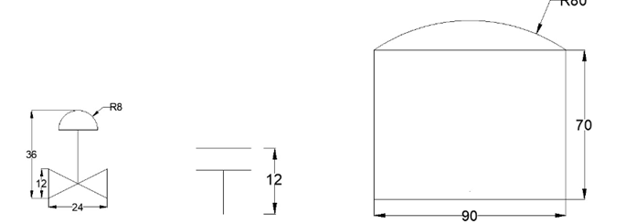
Start a new drawing file and create two blocks, as shown below.
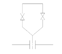
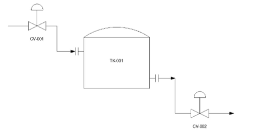
 Insert the blocks and create the drawing as shown below.
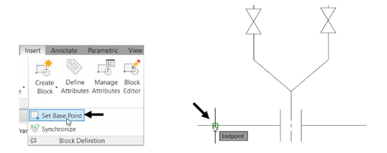
Expand the Block Definition panel and select the Set Base Point button.
Select the endpoint of the lower horizontal line as shown.
Click Insert > Block Definition > Write Block on the ribbon; the Write Block dialog box appears.
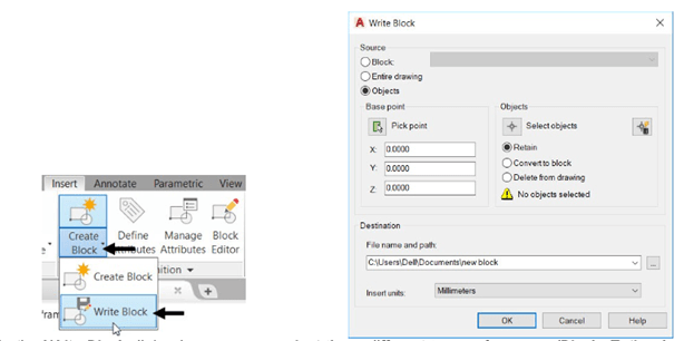
In the Write Block dialog box, you can select three different types of sources (Block, Entire drawing,
or Objects) to create a block. If you select the Block option, you can select blocks present in the
drawing from the drop- down.
Select the Entire drawing option.
Specify the location of the file and name it as Tap-in line.
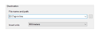
Click the OK button.
Close the drawing file.
Open a new drawing file, and then type I in the command line and press ENTER; the Insert
dialog box appears.
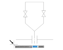
Select Tap-in line from the Name drop-down and click OK.
Pick a point in the drawing window to insert the block.
Defining Attributes
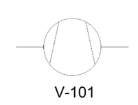
An attribute is a line of text attached to a block. It may contain any type of information related to a
block. For example, the following image shows a Compressor symbol with an equipment tag. The
procedure to create an attribute is discussed in the following example.
Example:
Open a new drawing file.
Create the symbols as shown below.
Click Insert > Block Definition > Define Attributes on the ribbon; the Attribute Definition
dialog box appears.
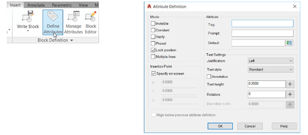
The options in the Mode group of the Attribute Definition dialog box are used to set the display mode
of the attribute. If you select the Invisible option, the attribute will be invisible. The Constant option
makes the value of the attribute constant. You cannot change the value. The Verify option prompts
you to verify after you enter a value. The Preset option allows you to set a predefined value for the
attribute. The Lock position option fixes the position of the attribute to a selected point. The Multiple
lines option allows typing the attribute value in single or multiple lines.
Ensure that the Lock position option is selected.
The options in the Attribute group are used to specify the values of the attribute. The Tag box is used
to enter the label of the attribute. For example, if you want to create an attribute called RESISTANCE,
you need to type Resistance in the Tag box. The Prompt box is used to specify the prompt message
that appears after placing the block. The Default box is used to specify the default value of the
attribute.
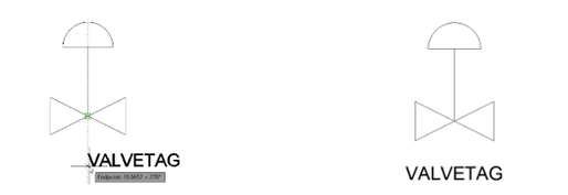
In the Attribute Definition dialog box, enter Valvetag in the Tag box.
The Text Settings options are used to specify the display properties of the text such as style, height
and so on. Observe the other options in this dialog box. Most of them are self-explanatory.
Enter 4 in the Text Height box.
Set the Justification to Middle and click OK.
Specify the location of the attribute as shown below.
Click the Create Block button on the Block Definition panel; the Block Definition dialog box appears.
Click on the Select Object button from the dialog box.
Note: If you want to use these blocks in any other drawings then instead of using Create Block
tool, you need to use Write Block tool, as discussed earlier.
Drag a window and select the control valve symbol and attribute. Press ENTER.
Select the Delete option from the Objects group.
Click the Pick Point button under the base point group and select the point as shown below.
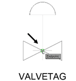
Enter Control Valve in the Name box and click OK.
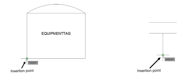
Similarly, create Equipmenttag and place inside the tank symbol.
Create a block and name it as Tank, as shown.
Also, create a block of the nozzle symbol and name it Nozzle, as shown.
Inserting Attributed Blocks
You can use the INSERT command to insert the attributed blocks into a drawing. The procedure to
insert attributed blocks is discussed next.
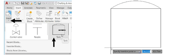
Click the Insert button with drop-down from the Block panel to expand it.
Click on the Tank block and click anywhere in the drawing area to specify the insertion point, as
shown.
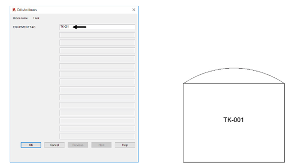
Enter TK-001 in the EQUIPMENTTAG field of the Edit Attributes dialog box displayed, as shown.
Click OK from the dialog box; the block will be placed along with the attribute.
Similarly, place control valves as shown below.
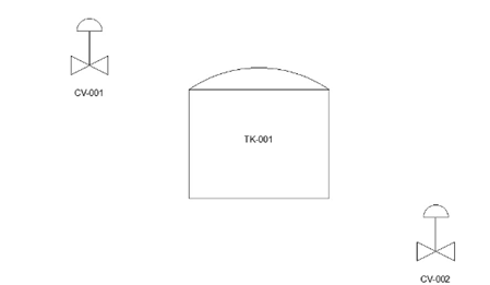
Now, place the nozzles on the tank as shown below.

Use the Polyline tool and connect the control valve and tank.
Working with External references
In AutoCAD, you can attach a drawing file, image or a pdf file to another drawing. These
attachments are called External References (Xrefs). They are dynamic in nature and update
automatically when changes are made to them. The following example, you will learn to attach
drawing files to a drawing.
Example:
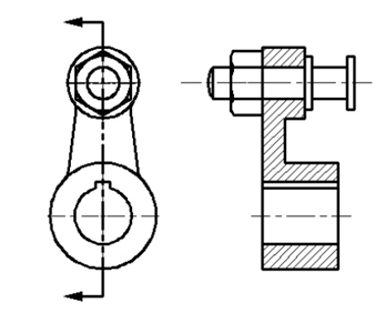
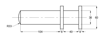
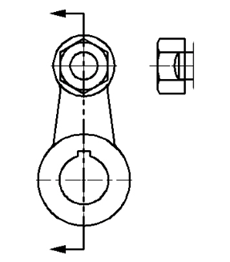
Create the drawing shown below.
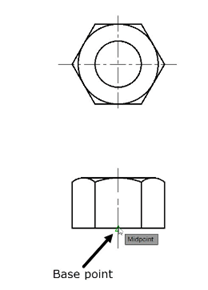
Type BASE in the command line and press ENTER.
Select the midpoint of the vertical line as the base point, as shown.
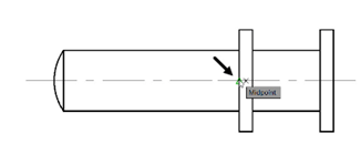
Save the drawing as Crank pin.dwg
Create another drawing as shown below.
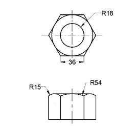
Use the Set Base Point tool and specify the base point as shown below.
Save the drawing as Nut.dwg and close it.
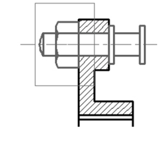
Open the Crank.dwg file created in Chapter 8.
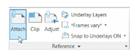
Click Insert > Reference > Attach on the ribbon; the Select
Reference file dialog box appears.
Browse to the location of the Crankpin.dwg and double-click on it; the Attach External
Reference dialog box appears.
Some of the options available in this dialog box are similar to that in the Insert dialog box, such as
the insertion point, scale, and rotation angle of the external reference.
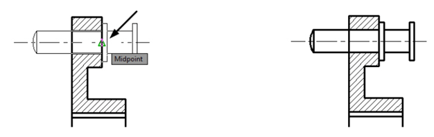
Accept the default settings in this dialog box and click OK; the crank pin will be attached to the
cursor.
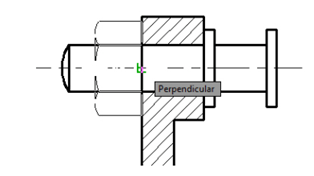
Select the point on the section view as shown below.
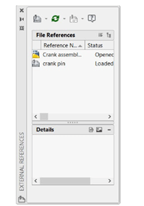
Click View > Palettes > External References Palette on the ribbon; the External
References Palette appears. This palette displays the Xrefs attached to the drawing.
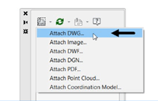
 In the External References palette, open the Attach drop-down and select the Attach DWG
option; the Select References file dialog box appears.
Browse to the location of the Nut.dwg and double-click on it; the Attach External Reference
dialog box appears.
In the Attach External Reference dialog box, enter 90 in the Angle box under the Rotation
group and click OK.
Select the insertion point on the section view as shown below.
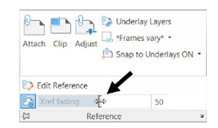
Fading an Xref
You can change the fading of Xref by using the Xref fading slider available in the expanded Reference panel.
Expand the Reference panel of the Insert ribbon and use the Xref fading slider to adjust the fading.
 Clipping External References
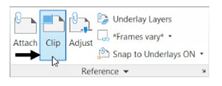
You can hide the unwanted portion of an external reference by using the Clip tool.
Click Insert > Reference > Clip on the ribbon; the message,
“Select Object to clip” appears in the command line.
Select the Nut.dwg from the drawing window.
Select the New boundary option from the command line.
Select the Rectangular option from the command line.
Draw a rectangle as shown below; only the front view of the nut is visible and the top view is
hidden. Also, the clipping frame is visible.
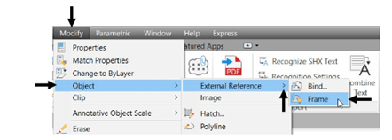
To hide the clipping frame, type XCLIPFRAME in the command line
Type 0 and press ENTER.
You can also hide the frame by clicking Modify > Object > External Reference > Frame on the
Menu Bar.
Attach another instance of the Nut.dwg file.
Use the Rotate and Move tools to position the top view as shown below.
Use the Clip tool and clip the Xref.