Section Views in AutoCAD
In this chapter, you will learn the following tools:
Create Section Views
Set Hatch Properties
Use Island Detection tools
Create text in Hatching
Edit Hatching
Section Views
In this chapter, you will learn to create section views, which are created by cutting an object along an imaginary cutting plane in order to view its interiors that cannot be shown clearly by means of hidden lines. In a section view, section lines, or cross-hatch lines, are added to indicate the surfaces that are cut by the imaginary cutting plane. In AutoCAD, you can add these section lines or cross-hatch lines using the Hatch tool.
The Hatch tool
The Hatch tool is used to generate hatch lines by clicking inside a closed area. When you click inside a closed area, a temporary closed boundary will be created using the PLINE command. The closed boundary will be filled with hatch lines, and then it will be deleted.
Example 1:
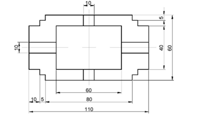
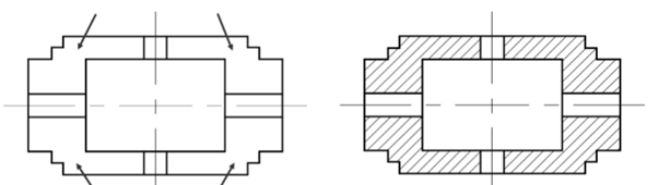
In this example, you will apply hatch lines to the drawing as shown in figure below.
Open a new AutoCAD file.
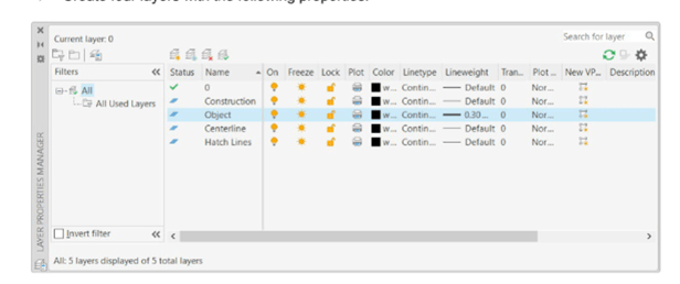
Create four layers with the following properties.
Create the drawing as shown below. Do not apply dimensions.
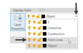
Select the Hatch lines layer from the Layer drop-down.
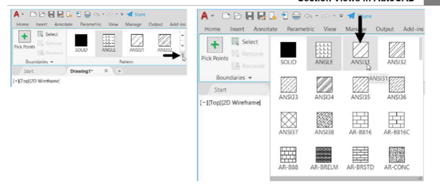
Click Home > Draw > Hatch on the ribbon or enter H in the command line; the Hatch
Creation tab appears in the ribbon.
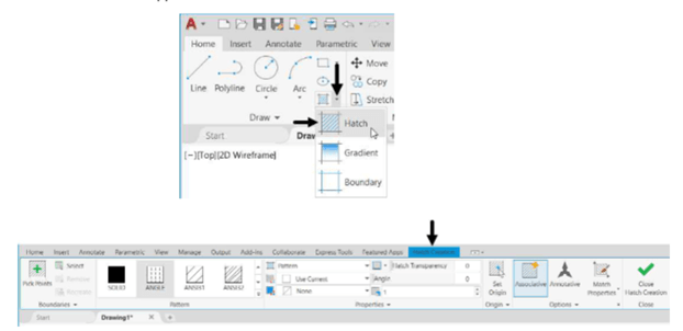
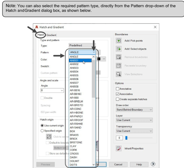
Select ANSI31 from the Pattern panel of the Hatch Creation ribbon, as shown. You can display other hatch patterns available in it, as shown.
Click in the four areas of the drawing, as shown below.
Right-click and select Enter.
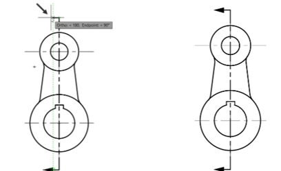
Example 2:
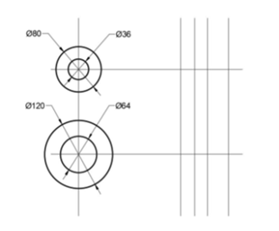
In this example, you will create the front view and section view of a crank.
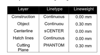
Create five layers with the following settings:
Set the Construction layer as the current and create construction lines as shown.
Set the Object layer as the current and create draw circles as shown.
Switch to Construction layer and create construction lines as shown.
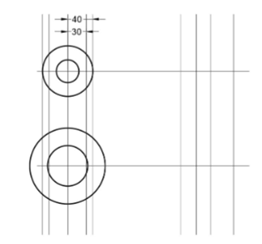
Switch to Object layer and create two lines as shown.
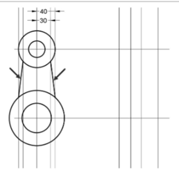
On your own, create other objects on the front view as shown.
On your own, create the objects of the section view as shown.
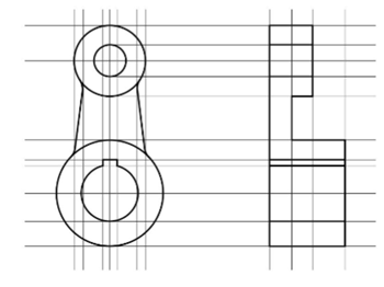
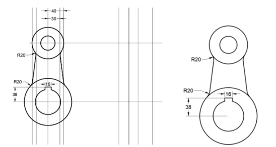
Set the Centerlines layer as current and create center marks and centrelines.
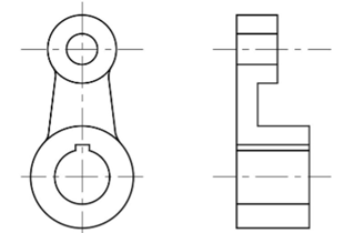
Set the Cutting Plane layer as current.
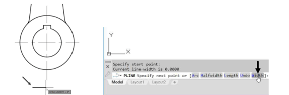
Click the Polyline button on the Draw panel and pick a point below the front view as shown.
Select the Width option from the command line.
Type 0 as the starting width and press ENTER.
Type 10 as the ending width and press ENTER.
Move the cursor horizontally toward right and enter 20.
Again, select the Width option from the command line.
Set the starting and ending width to 0.
Move the cursor horizontally and click when trace lines are displayed as shown below.
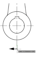
Move the cursor vertically up and click.
Move the cursor toward left and click when trace lines are displayed from the endpoint of
the lower horizontal line.
Create another arrow by changing the width of the polyline.
Set the Hatch Lines layer as current.
Type H in the command line and press ENTER.
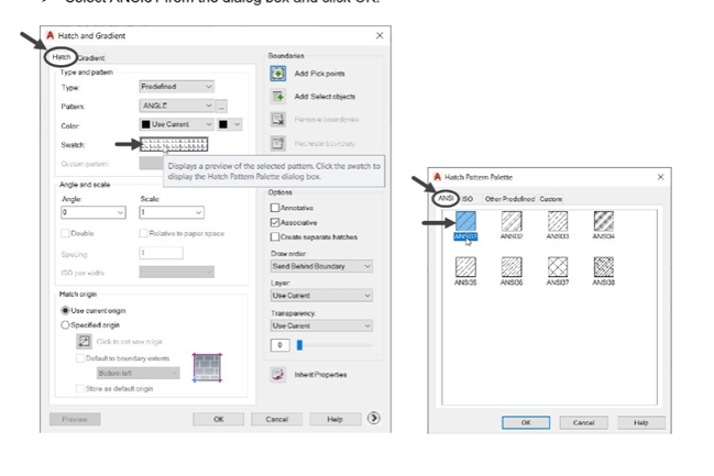
Select the SeTtings option from the command line; the Hatch and Gradient dialog box appears.
Click on the Swatch box under the Type and pattern group; the Hatch Pattern Palette
dialog box appears.
Select ANSI31 from the dialog box and click OK.
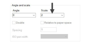
Set the Scale value to 2 under Angle and scale area of the Hatch and Gradient dialog box.
Click the Add Pick Points button from the Boundaries group and click in Region 1, Region 2 and
Region3.
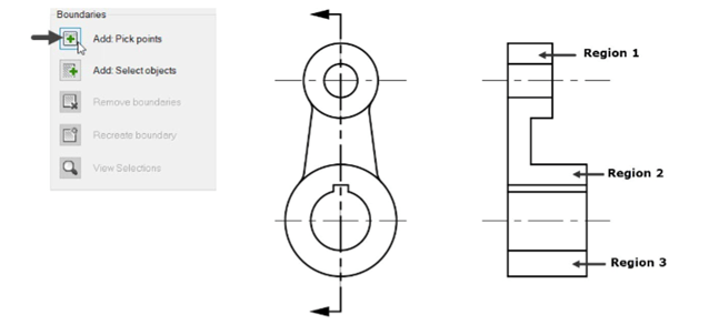
Press ENTER to create hatch lines.
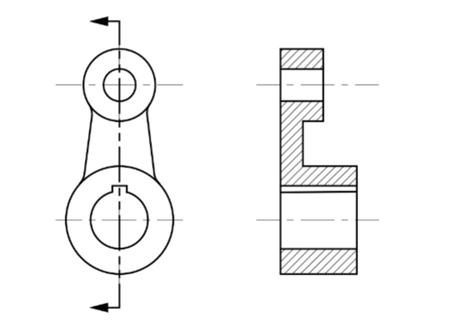
Save the drawing as Crank.dwg and close.