Geometric Dimensioning and Tolerancing
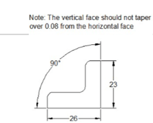
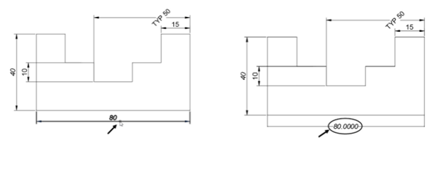
Earlier you have learned how to apply tolerances to the size (dimensions) of a component. However, the dimensional tolerances are not sufficient for manufacturing a component. You need to give tolerance values to its shape, orientation and position as well. The following figure shows a note which is used to explain the tolerance value given to the shape of the object.
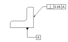
Providing a note in a drawing may be confusing. To avoid this, we use Geometric Dimensioning and Tolerancing (GD&T) symbols to specify the tolerance values to shape, orientation and position of an object. The following figure shows the same example represented by using the GD&T symbols. In this figure, the vertical face to which the tolerance frame is connected, must be within two parallel planes 0.08 apart, perpendicular to the datum reference (horizontal plane).
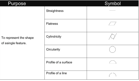
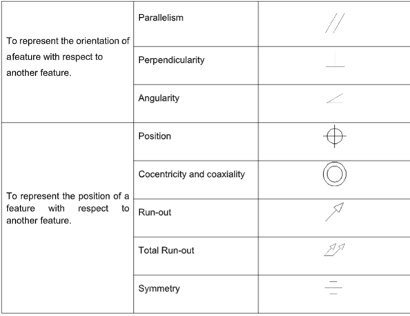
The Geometric Tolerancing symbols that can be used to interpret the geometric conditions are given
in the table below.
Example:
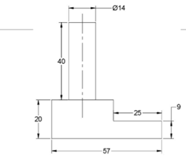
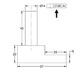
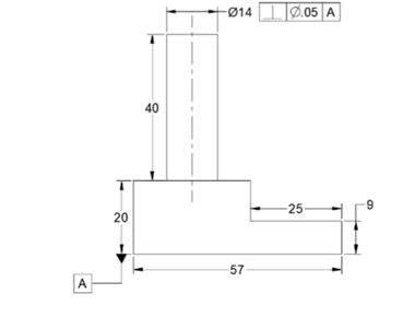
In this example, you will apply geometric tolerances to the drawing shown below.
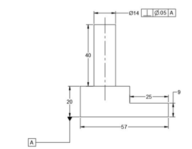
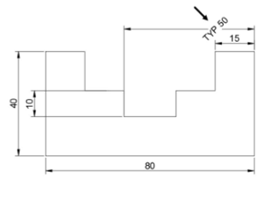
Create the drawing as shown below.
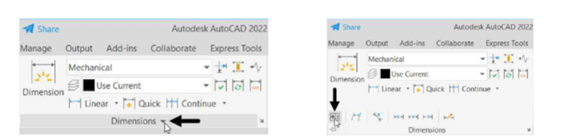
Click on the Dimensions down-arrow from the Annotate tab to expand it, as shown.
Next click on the Tolerance button, as shown; the Geometric Tolerance dialog box get
displayed.
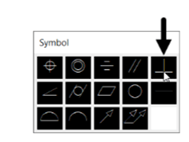
In the Geometric Tolerance dialog box, click on the upper box of the Sym group; the Symbol
dialog box appears.
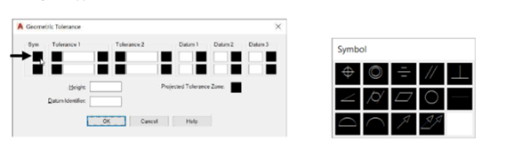
In the Symbol dialog box, click the Perpendicularity symbol; the symbol appears in the Sym group.
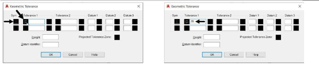
Click in the top left box of the Tolerance 1 group; the diameter symbol appears in the box.
Enter .05 in the box next to the diameter symbol.
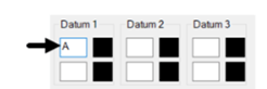
 Enter A in the upper box of the Datum 1 group.
 Click OK and place the Feature Control frame as shown below.
Next, you need to add the datum reference.
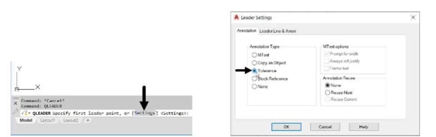
Type QLEADER in the command line and press ENTER.
Select Settings from the command line; the Leader Settings dialog box appears.
In the Leader Settings dialog box, select the Tolerance option.
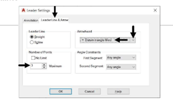
 Click the Leader Line & Arrow tab and set the Arrowhead type to Datum triangle filled.
Set Number of Points to 3.
Click OK and specify the first, second and third points of the datum reference as shown
below; the Geometric Tolerance dialog box appears.
In the Geometric Tolerance dialog box, set Datum Identifier to A.
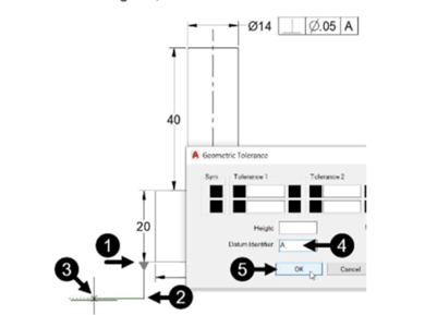
Click OK.
Editing Dimensions by Stretching
In AutoCAD, the dimensions are associative to the drawing. If you modify a drawing, the dimensions
will be modified, automatically. In the following example, you will stretch the drawing to modify the
dimensions.
Example:
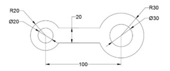
Create the drawing as shown below and apply dimensions to it.
 Click Home > Modify > Stretch on the ribbon.
Drag a window over the right-side circles and the horizontal lines to select them.
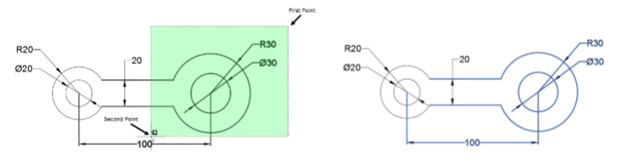
Right-click and select the center point of the right-side circles.
Move the cursor to stretch the drawing; you will notice that the horizontal dimension also changes.
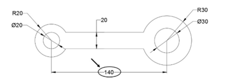
Type 40 and press ENTER; the horizontal dimension is updated to 140.
Modifying Dimensions by Trimming and Extending
In earlier chapters, you have learned to the modify drawings by trimming and extending objects. In the
same way, you can modify dimensions by trimming and extending. The following example shows you
how to modify dimensions by this method.
Example:
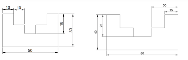
Create a drawing as shown below and add dimensions to it.
Select the horizontal edge as shown in figure and right-click to accept.
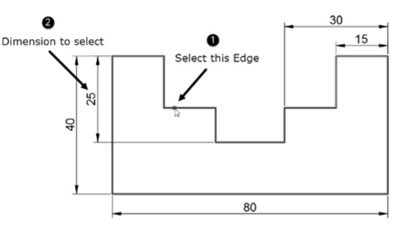
Select the vertical dimension with the value 25; it will be trimmed upto the selected edge.
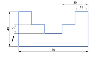
Press ESC.
Click Home > Modify > Trim > Extend from the ribbon.
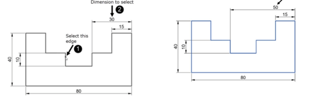
Select the vertical edge as the boundary, as shown below. Next, right-click to accept.
Select the horizontal dimension with the value 30; the dimension will be extended upto the
selected boundary.
Using the DIMEDIT command
The DIMEDIT command can be used to modify dimension. Using this command, you can add text to a
dimension, rotate the dimension text and extension lines or reset the position of the dimension text.
Example: (Adding Text to the dimension)
Type DED in the command line and press ENTER.
Select the New option from the command line; a text box appears.
Enter TYP in the text box and press the SPACEBAR.
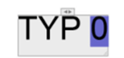
Left-click and select the dimension with value 50.
Press ENTER; the dimension text will be changed.
Example: (Rotating the dimension text)
Enter DED in the command line and select the
Rotate option; the message, “Specify angle for
dimension text” appears in the command line.
Type 45 and press ENTER.
Select the dimension with the value TYP 50 and
right- click; the angle of the dimension text is
changed to 45 degrees. Note that the angle is
measured from the horizontal axis (X-axis).
Using the Update tool
The Update tool is used to update a dimension with the currently active dimension style. For example, if
you have created new dimension style, you can apply it an already existing dimension using the Update
tool.
Example: (Update the dimension with current active style)
Type D in the command line and press ENTER; the Dimension Style Manager dialog box appears.
In the Dimension Style Manager dialog box, select Standard from the Styles list and click Modify.
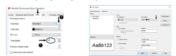
In the Modify Dimension Style dialog box, set the Text height to 2.5.
Click the Text Style button; the Text Style dialog box appears.
In the Text Style dialog box, change the Font Style to Italic.
 Click Apply and then Close from the Text Style dialog box.
Click OK from the Modify Dimension Style dialog box.
Next, click Close from the Dimension Style Manager dialog box to close it.
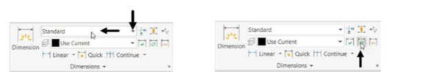
In the Dimensions panel, set the dimension style to Standard.
Click the Update button on the Dimensions panel.
Select the horizontal dimension with the value 30. Next, right-click; the dimension will be
updated with the current the dimension style.
Using the Oblique tool
The Oblique tool is used to incline the extension lines of a dimension. This tool is very useful while
dimensioning the isometric drawings. It can also be used in 2D drawings when the dimensions overlap
with each other.
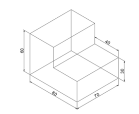
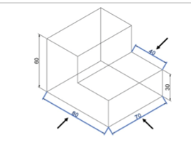
Example:
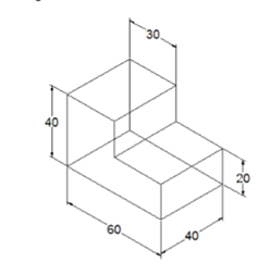
In this example, you will create an isometric drawing and add dimensions to it. Next, you will use the
Oblique tool to change the angle of the dimension lines.
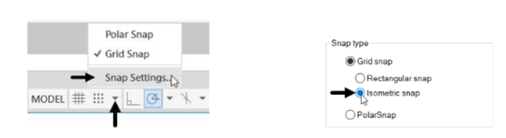
Click on the down arrow next to the SNAPMODE button from the status bar and select Snap
Settings; the Drafting Settings dialog box appears.
Alternatively, you can enter DS in the command line to display the Drafting Settings dialog box.
In the Drafting Settings dialog box, set Snap type to Isometric snap and click OK.
Turn on the Snap Mode [], Ortho Mode [], and the Dynamic Input
[]. You can simply press F9, F8, and F12 key to activate.
Click Zoom All on the Navigation Bar.
Type L in the command line and press ENTER.
Click at a random point and move the cursor vertically upwards.
Type 60 in the command line and press ENTER; a vertical line will be created.
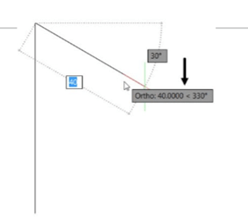
Move the cursor toward right; you will notice that an inclined line is attached to the cursor.
Click when the tooltip shows 40 < 330.
Move the cursor toward downward and click when the tooltip shows 30 < 270.
Move the cursor toward right and click when the tooltip displays 40 < 330.
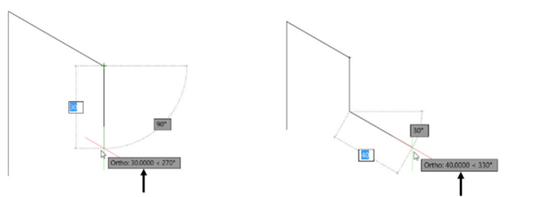
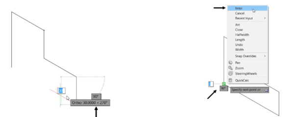
Move downward and click when the tooltip shows 30 < 270.
Move the cursor toward left and click on the start point of the sketch.
Right-click select Enter.
Turn off the Ortho Mode.
Drag a selection window and select all the objects of the sketch.
Right-click and select Copy-Selection from the shortcut menu.
Select the lower left corner point as the base point.
Move the cursor toward right and click when the tooltip shows 70 < 30.
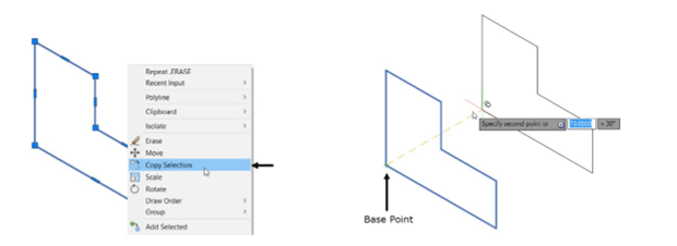
Right-click and select Enter.
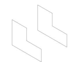
Use the Line tool and connect the endpoints of the two sketches.
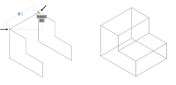
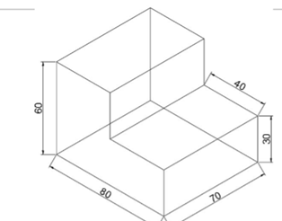
Use the dimensioning tools and apply dimensions to the sketch.
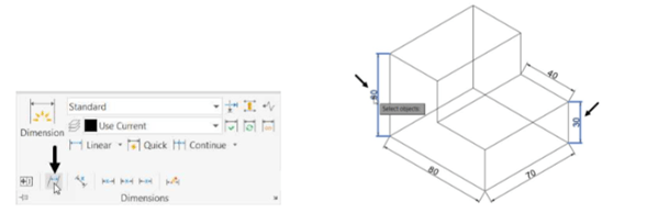
Expand the Dimensions panel on the Annotate ribbon and click the Oblique button.
Select the vertical dimensions and right-click to accept; the message, “Enter obliquing angle”
appears in the command line.
 Type 150 as the oblique angle and press ENTER; the dimensions are oblique as shown below.
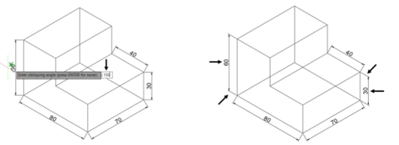
Again, click the Oblique tool from the Dimensions panel and select the aligned dimensions.
Next, right- click to accept.
Type 90 as the oblique angle and press ENTER; the dimensions will be oblique as shown below.