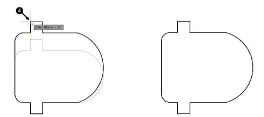
The Explode tool
The Explode tool is used to explode a group of objects into individual objects. For example,
when you create a d rawing using the Polyline tool, it acts as a single object. You can
explode a polyline or rectangle or any group of objects using the Explode tool.
Click on the portion of the drawing created using the Polyline tool; you will notice that it is
selected as a single object.
Click Home > Modify > Explode on the ribbon or enter X in the command line.
Select the polylines from the drawing.
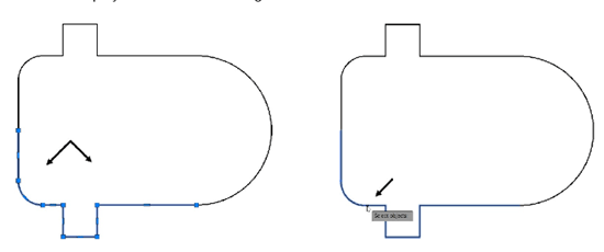
Press ENTER; the polyline is exploded into individual objects.
Now, you can select the individual objects of the polyline. You can also select the top polyline
and few objects of bottom polyline to note the difference between top and bottom polyline
(exploded), as shown.
The Stretch tool
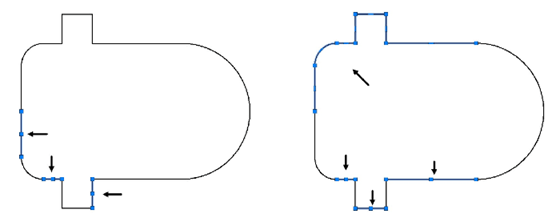
The Stretch tool is used to lengthen or shorten drawings or parts of drawings. Note that
you cannot stretch circles using this tool. Also, you need to select the portion of the drawing to be stretched by dragging a window.
Click Home > Modify > Stretch on the ribbon or enter STRETCH in the command line.
Drag a crossing window to select the objects of the drawing.
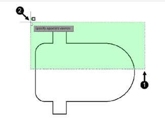
Press ENTER or right-click to accept the selection.
Select the base point as shown below.
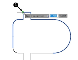
Move the cursor upwards and click to stretch the drawing.
Save and close the file.
Note: If you select the whole model or all entities of a model then, Stretch tool will work like a Move tool.
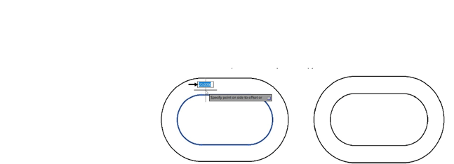
The Offset tool
The Offset tool is used to create parallel copies of lines, polylines, circles, arcs and so on. To
create parallel copy of an object, first you need to specify the offset distance, and then select the
object. Next,
you need to specify the side in which the parallel copy will be placed.
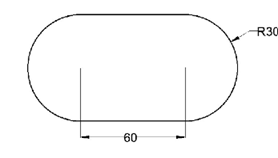
Create the drawing shown below using the Polyline tool.
Click Home > Modify > Offset on the ribbon or enter O in the command line.
Type 20 as the offset distance and press ENTER.
Select the polyline loop.
Click outside the loop to create the parallel copy.
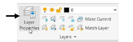
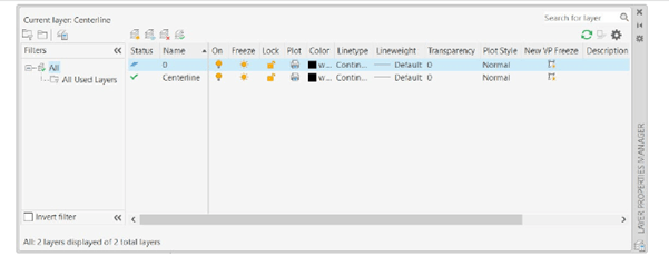
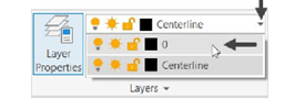
Click Home > Layer > Layer Properties on the ribbon LA in the command line; the Layer
Properties Manager appears.
Click the New layer button on the Layer Properties Manager. Enter Centerline in the Name
field.
Click the Set Current button on the Layer Properties Manager; a new layer is created
and is set as current.
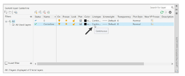
Click in the Linetype field of the current layer; the Select Linetype dialog box appears.
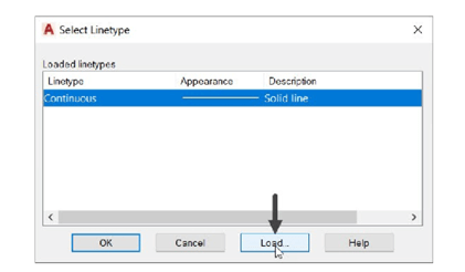
On the Select Linetype dialog box, click the Load button; the Load or Reload Linetypes
dialog box appears.
Select the CENTER2 linetype from this dialog box and click OK button; the linetype is
added to the Select Linetype dialog box.
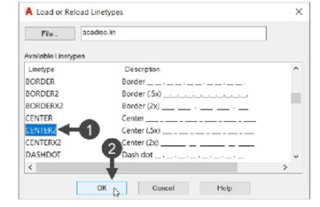
Select the CENTER2 linetype from the Select Linetype dialog box and click OK.
Close the Layer Properties Manager.
Click the Offset button on the Modify panel.
Select the Layer option from the command line.
Select the Current option from the command line; this ensures that the offset entity will be
created with the currently set layer properties. If you select the Source option, the offset entity
will be created with the properties of the source object.
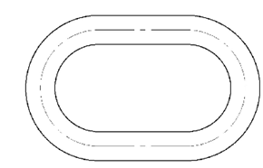
Select the outer loop of the drawing.
Move the cursor inwards and click to create the offset entity.
Alternatively, you can select the inner loop and move the cursor outwards to create the
offset entity.
Click on the Layer drop-down on the Layer panel of the ribbon.
Select the 0 layer from the drop-down.
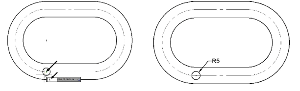
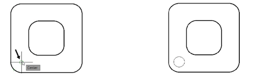
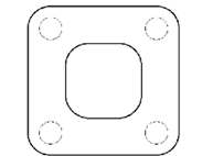
Create a circle of 10 mm diameter, as shown.
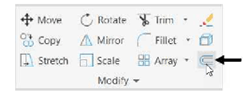
The Rectangular Array tool
The Rectangular Array tool is used to create an array of objects along the X and Y directions.
Open a new AutoCAD file and draw the sketch shown below.
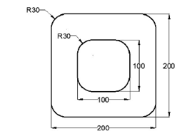
Draw a circle of 30 mm diameter concentric to the fillet.
Click Home > Modify > Array > Rectangular Array on the ribbon or enter ARRAYRECT in
the command line.
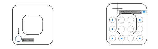
Also, the Array Creation tab appears, as shown.
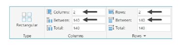
Set the Columns count to 2.
Set the Rows count to 2.
Set the Between value in the Columns panel to 140.
Set the Between value in the Rows panel to 140.
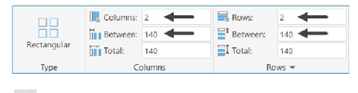
Click Close Array on the ribbon.
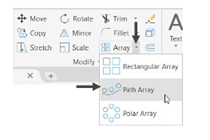
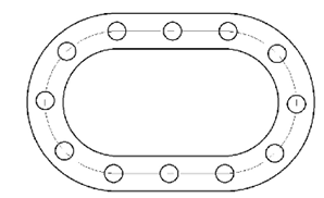
The Path Array tool
The Path Array tool is used to create an array of objects
along a path (line, polyline, circle, helix, spline etc.)
Click Home > Modify > Array > Path Array on the ribbon or
enter ARRAYPATH in the command line.
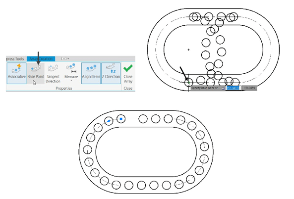
Select the circle and right-click (in previously created while
using the Offset tool).
Select the centerline as the path; the preview of the path array appears in asymmetric order.
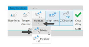
Select the Base Point button from the Properties panel of the Array Creation tab.
Next, select the center point of the circle with 5 mm radius; the path array will get arranged
symmetrical, as shown.
the path array.
If you select the Measure method, you need to enter the distance between the items in the path
array.
Set the Items count to 12.
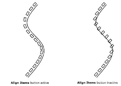
Notice that the Align Items button is active by default. As a result, the items are aligned with
the path. If you deactivate this button, the items will not be aligned with the path.
Click the Close Array button.
Save and close the file.