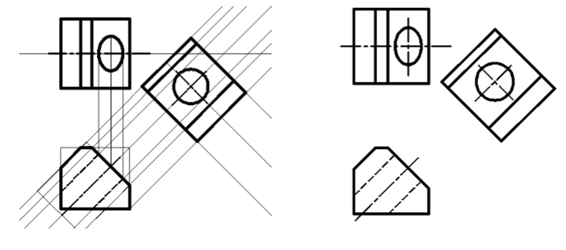
Creating Auxiliary Views
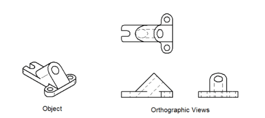
Most of the objects are represented by using orthographic views (front, top and/or side views). But many objects have features located on inclined faces. You cannot get the true shape and size forthese features by using the orthographic views. To see an accurate size and shape of the inclined features, you need to create an auxiliary view. An auxiliary view is created by projecting the object onto a plane other than horizontal, front or side planes. The following figure shows an object with an inclines face. When you create orthographic views of the object, you will not be able to get the true shape of the hole on the inclined face.
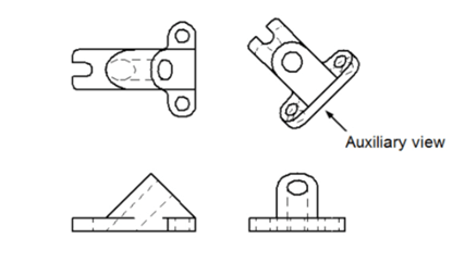
To get the actual shape of the hole, you need to create an auxiliary view of the object as shown below.
Example:
In this example, you will create an auxiliary view of the object shown below.
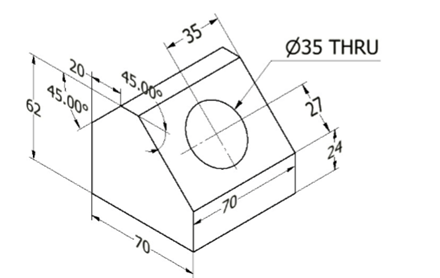
Open a new AutoCAD file.
Create four new layers with the following properties.
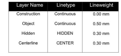
Select the Construction layer from the Layer drop-down in the Layer panel.
Create a rectangle at the lower left corner of the drawing window, as shown in figure.
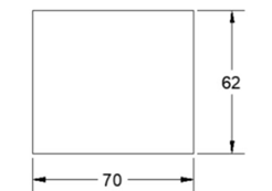
Select the rectangle and click the Copy button from the Modify panel.
Select the lower left corner of the rectangle as the base point.
Make sure that the Ortho mode is activated.
Move the cursor upward and type 25 in the command line. Next, press ENTER.
Press ESC to exit the Copy tool.
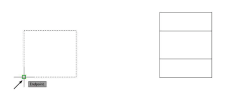
Click the Rotate button on the Modify panel and select the copied rectangle. Press ENTER to
accept.
Select the lower right corner of the rectangle as the base point.
Type 45 as the angle and press ENTER.
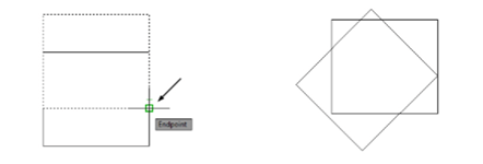
Create another rectangle approximately 60 mm above the previous one, as shown.

The rectangle located at the top is considered as top view and the below it is the front view.
Click the Explode button on the Modify panel and select the newly created rectangle. Next,
right-click to explode the rectangle.
Use the Offset tool and offset the vertical lines of the rectangle.
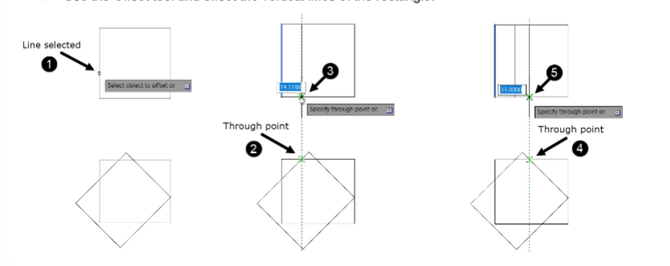
Select the Object layer from the Layer drop-down in the Layer panel.
Create the object lines in the front and top views as shown below.
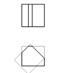
Select the Construction layer from the Layer panel.
Click the Construction Line button on the Draw panel.
Select the Offset option from the command line. Next, select the Through option.
Select the inclined line on the front view. Next, select the intersection point as shown below.
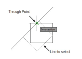
Similarly, create other construction lines as shown below.
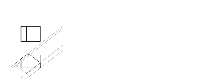
Create other construction lines as shown below.
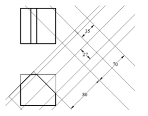
Set the Object layer as current layer. Next, create the object lines using the intersection points
between the construction lines.
Use the Circle tool and create a circle of the 35 mm.
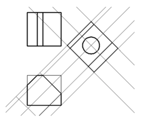
Set the Construction layer as current layer. Create projection lines from the circle.
On your own, create the other object lines, hidden lines, and center lines, as shown below.
Drawing after hiding the Construction layer is shown below.
