Drawing Basics in AutoCAD
In this chapter, you will learn to do the following:
Draw lines, rectangles, circles, ellipses, arcs, polygons, and polylines
Use the Erase, Undo and Redo tools
Draw entities using the absolute coordinate points
Draw entities using the relative coordinate points
Draw entities using the tracking method
Drawing Basics
This chapter teaches you to create simple drawings. You will create these drawings using the basic
drawing tools. These tools include Line, Circle, Polyline, and Rectangle and so on and they are
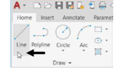
available in the Draw panel of the Home tab in the ribbon, as shown below. You can also invoke
these tools by typing them in the command line, as shown.

Drawing lines
You can draw a line by specifying its start point and end point using the Line tool. However, there are
various methods to specify start and end points of a line. These methods are explained in the
following examples.
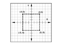
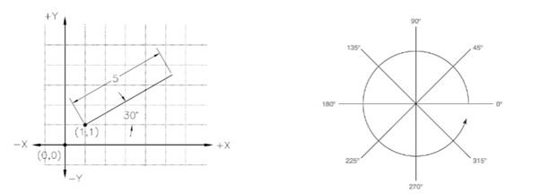
Example (using the Absolute Coordinate System):
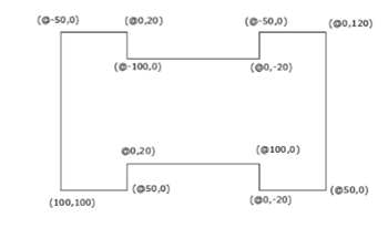
In this example, you will create lines by specifying points in the absolute coordinate system. In this
system, you specify the points with respect to the origin (0,0). A point will be specified by entering its
X and Y coordinates separated by a comma, as shown in figure below.
Start AutoCAD 2022 by clicking the AutoCAD 2022 icon on your desktop.
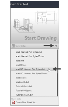
On the Welcome screen, click Start Drawing > Templates > acadISO-Named Plot
Styles.dwt, as shown. This starts a new drawing using the ISO template.
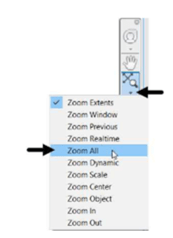
Click Zoom > Zoom All on the Navigation Bar; the entire area in the drawing window will be
displayed.
Turn OFF the Grid Display by pressing the F7 key.
Click the Customization button on the status bar, and then select the Dynamic Input option
from the flyout to display the Dynamic Input icon on the status bar, if it is not available.
Turn OFF the Dynamic Input mode, as shown.
You will learn about Dynamic Input later in this chapter.

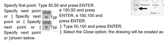
To draw a line, click Home > Draw > Line on the ribbon, or enter LINE or L in the command line.
Follow the prompt sequence given next.

Click Save on the Quick Access Toolbar to display the Save Drawing As dialog box.

Enter Line-example1 in the dialog box and click on the Save button to save it, as shown.
Click on icon to close the file, as shown.

Example (using Relative Coordinate system):
In this example, you will draw lines by specifying points in the relative coordinate system. In this
method, you specify the location of a point with respect to the previous point. For this purpose, the
symbol ‘@’ is used before the point coordinates. This symbol means that the coordinate values are
specified in relation with the previous point.
Click on New button from Quick Access Toolbar to display the Select template dialog box, as shown.
Select acadISO –Named Plot Styles template, as shown.
Next click on the Open button of the dialog box, as shown.

Type Z in the command line to invoke the ZOOM command.
Select the All option from the command line; the entire area in the drawing window will be displayed.
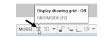
Press the F7 key to turn OFF the Display drawing grid mode,
if active. Alternatively, you can deactivate it from the status bar, as shown.
Turn OFF the Dynamic Input mode, if active.
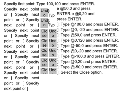
Click Home > Draw > Line on the ribbon or enter LINE or L in the command line.
Follow the prompt sequence given next.
Save the file as Line-example2.dwg.
Close the file.
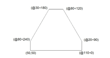
Example (using Polar Coordinate system):
In the polar coordinate system, you specify the location of a point by entering two values: distance
from the previous point and angle from the zero degrees. You enter the distance value along with the
“@” symbol and angle value with the “<” symbol. Note that angles in AutoCAD are measured in anti-
clockwise direction.
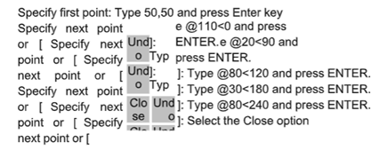
Drawing Task
Open a new file using the acadISO -Named Plot Styles template.
Click Zoom > Zoom All on the Navigation Bar.
Turn OFF the Grid icon on the status bar.
Turn OFF the Dynamic Input mode, if active.
Click Home > Draw > Line on the ribbon or enter LINE or L in the command line.
Follow the prompt sequence given next.
Save the file as Line-example3.dwg.
Close the file.
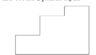
Example (using Direct Distance Entry):
In the direct distance entry method, you draw a line by entering its distance and angle values. Note
that you need to turn ON the Dynamic Input.
Open a new file using the acadISO -Named Plot Styles template.
Turn-off the Grid and Snap Mode at the Status Bar.
Click Zoom > Zoom All on the Navigation Bar.
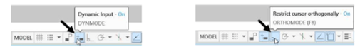
Activate the Dynamic Input button and ORTHOMODE button on the Status Bar, as shown.
Click Home > Draw > Line on the ribbon or enter LINE or L in the command line.
Specify the first point of the line by typing 50,50 and pressing ENTER.
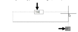
Move the cursor horizontally toward right and type 150 as length.
Press the TAB key and type 0 as angle, if required. Next, press ENTER.
Move the cursor vertically upwards and type 100 as length.
Press the TAB key and type 90 as angle. Next, press ENTER.
Move the cursor horizontally toward left and type 50.
Press the TAB key and type 180 as angle. Next, press ENTER.
Move the cursor vertically downwards and type 20.
Press the TAB key and type 90 as angle. Next, press ENTER.
Move the cursor horizontally toward left and type 50.
Press the TAB key and type 180 as angle. Next, press ENTER.
Move the cursor vertically downwards and type 40.
Press the TAB key and type 90 as angle. Next, press ENTER.
Move the cursor horizontally toward left and type 50.
Press the TAB key and type 180 as angle. Next, press ENTER.
Select the Close option from the command line.
Save the file as Line-example4.dwg and close it.