-
 MS Office Home & Business 2024 – Lifetime License Key – Mac/PC$150.00 – $160.00
 -
![Design for Torsion 4 [Retail] Office 2021/2019/2016 Pro Plus Activates 5 PCs Online](https://civilmdc.com/wp-content/uploads/2024/05/Microsoft-Office-professional-plus-all-in-one-free-download-e1717158603220-300x300.jpg) [Retail] Office 2021/2019/2016 Pro Plus Activates 5 PCs Online$50.00 – $120.00
[Retail] Office 2021/2019/2016 Pro Plus Activates 5 PCs Online$50.00 – $120.00 -
 Microsoft office /Windows Activation Service for Phone Activation Method (Get Confirmaiton ID)$3.00
 -
 MS SQL Server 2022 Standard | 1 Key for 1 PC$80.00
 -
 Youtube Premium | 4 months Premium Membership$10.00
 -
Product on sale
 Adobe Stock 40 creditsOriginal price was: $99.00.$20.00Current price is: $20.00.
 -
Product on sale
 MS Office 2021 Home & Business 1 MAC Bind for iOSOriginal price was: $429.00.$85.00Current price is: $85.00.
 -
 MS Office 365 Personal | Family Plan on Your Email Id – 1 Year subscription$30.00 – $66.00
 -
 MS Project Professional 2024 | 2021 | 2019 | 2016 1 PC Online key Activation$20.00 – $80.00
 -
Product on sale
 Adobe Creative Cloud (All apps) – PersonalOriginal price was: $560.00.$200.00Current price is: $200.00.
 -
 Windows Server 2019 Online Key$22.00
 -
 MS Office Visio Professional 2024 | 2021 | 2019 | 2016 PC Online Key Activation$20.00 – $80.00
 -
Product on sale
 MS 2019 Project Professional Windows 1 PC Online keyOriginal price was: $429.00.$22.00Current price is: $22.00.
 -
 McAfee LiveSafe Internet Security Antivirus 1 PC – 10 YEARS – Key$29.00
 -
 Office Professional 2016 /2013/2010 – Lifetime License Key – 1PC$14.00 – $16.00
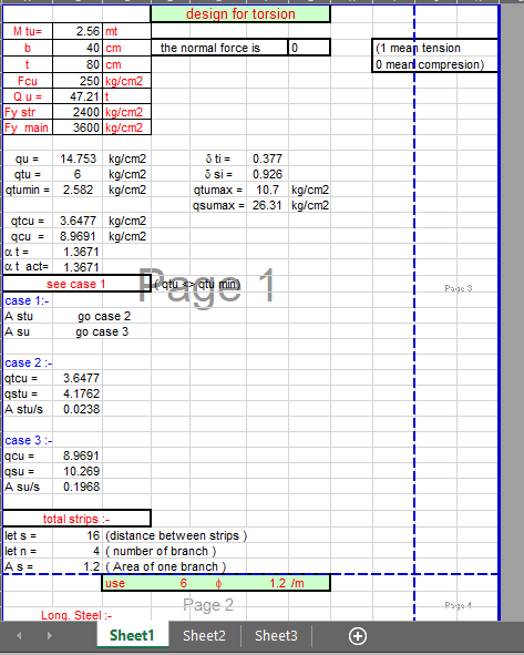
Designing for torsion involves determining the required reinforcement to resist the twisting forces acting on a structural member. Here’s a step-by-step guide to designing for torsion:
Determine the applied torsional moment: Identify the magnitude and direction of the applied torsional moment on the structural member. This can be due to various factors such as eccentric loading, wind loads, or seismic forces.
Calculate the torsional shear stress: Calculate the torsional shear stress induced by the torsional moment. This can be done using the formula:
τ = Tc / J
where:
τ = Torsional shear stress
Tc = Applied torsional moment
J = Polar moment of inertia of the cross-section
Check the torsional capacity: Determine the torsional capacity of the member by referring to design codes or guidelines specific to the material being used. The torsional capacity is the maximum allowable torsional shear stress the member can withstand without failure.
Determine the required reinforcement: If the torsional shear stress exceeds the torsional capacity, reinforcement is required to increase the member’s torsional strength. Design codes provide guidelines for calculating the required amount of reinforcement based on factors such as the applied moment, material properties, and design criteria.
Select the type of reinforcement: Depending on the specific design requirements and constraints, various types of reinforcement can be used to increase torsional strength. This may include adding steel bars, helical reinforcement, or using composite materials.
Design the reinforcement layout: Determine the layout of the reinforcement, including the number, size, and spacing of bars. Consider the compatibility with other design requirements and construction constraints. Proper detailing, such as lap lengths, anchorage lengths, and curtailment points, should also be considered.
Check for serviceability requirements: In addition to strength requirements, it’s essential to check the serviceability aspects of the member under torsional loading. This includes checking for deflection limits, cracking control, and vibration considerations, if applicable.
Prepare construction drawings: Prepare detailed construction drawings that illustrate the dimensions, reinforcement layout, and any additional detailing required to accommodate the torsional reinforcement.
-
 Bitdefender Total Security Antivirus | Genuine Activation Code$30.00
 -
 IDEA StatiCa Education$30.00
 -
 Stealth Writer AI | Bypass AI Detection | Get 100% Human Score$10.00
 -
 Adobe Acrobat XI Professional with License Key Activation$29.00
 -
 Autocad 2007 – OFFLINE INSTALLER + Video Tutorial Install and activation – LIFETIME$7.00
 -
 ChatGPT PLUS Subscription$7.00
 -
 ESET Internet Security Antivirus | 1 Year License$20.00
 -
 Course Hero Account
1 month
$10.00 -
 General Software Collection | Request books, Codes, Research Articles | Request Software on Demand$3.00 – $35.00
 -
 Vmware Workstation 16 Pro Lifetime License$150.00 – $199.00
 -
 NORD VPN/IP Vanish Account Subscription 6 Month | 1 Year | 2 Years$20.00 – $60.00
 -
 Internet Download Manager IDM Version 6.41 fully lifetime activation with installation video | 5 times faster download (Pre-Activated)$6.00
 -
 Adobe Acrobat Pro DC 2024 | 2023 | 2022 | 2021 | 2020 | Latest Full Version | Lifetime$10.00 – $20.00
 -
![Design for Torsion 31 Sketch Up Pro 2025 | 2024 | 2023 | 2022 | 2021 Full Package Bundle + Vray 7 + Enscape 4.4 + Thea Render 3.5 [Lifetime & Full]](https://civilmdc.com/wp-content/uploads/2022/03/SketchUp-2025-300x300.jpg) Sketch Up Pro 2025 | 2024 | 2023 | 2022 | 2021 Full Package Bundle + Vray 7 + Enscape 4.4 + Thea Render 3.5 [Lifetime & Full]$10.00 – $45.00
Sketch Up Pro 2025 | 2024 | 2023 | 2022 | 2021 Full Package Bundle + Vray 7 + Enscape 4.4 + Thea Render 3.5 [Lifetime & Full]$10.00 – $45.00 -
 Adobe 2024 | 2023 | 2022 Full Collection$25.00 – $35.00


 Visit
Visit 